Calibrating Ultrasonic Level
Calibrating Ultrasonic Level: A Comprehensive Engineering Guide for Industrial Applications
In the landscape of industrial automation, precise liquid and solid level measurement is fundamental to process efficiency, safety, and inventory management. Among the various technologies available, Ultrasonic Level Meters have emerged as a preferred solution due to their non-contact nature, ease of installation, and cost-effectiveness. However, the inherent accuracy of these devices is heavily dependent on proper setup and commissioning.
Calibrating ultrasonic level instruments is not merely a one-time task during installation but a critical engineering procedure that accounts for environmental variables, vessel geometry, and the physical properties of the medium being measured. This guide provides a detailed technical overview of the principles, calibration procedures, and installation best practices required to ensure high-performance measurement.
Understanding the Measurement Principle
Before addressing the specifics of calibrating ultrasonic level sensors, it is essential to understand the underlying physics. Ultrasonic sensors operate on the "Time-of-Flight" (ToF) principle. The transducer emits a high-frequency acoustic pulse (typically between 20 kHz and 200 kHz) that travels through the air or gas space in a vessel, reflects off the surface of the material, and returns to the sensor.
The distance ($D$) from the sensor to the material surface is calculated using the formula:
$$D = \frac{c \times t}{2}$$
Where:
- $c$ is the speed of sound in the medium (usually air).
- $t$ is the total time elapsed between emission and reception.
The device then subtracts this distance from the total vessel height (the "Empty Distance" or $H$) to determine the level ($L$):
$$L = H – D$$
The Impact of the Speed of Sound
The accuracy of this calculation is entirely dependent on the speed of sound ($c$). In air at 20°C (68°F), sound travels at approximately 343 meters per second (m/s). However, the speed of sound is not constant; it fluctuates based on the temperature, humidity, and composition of the gas through which it travels. For instance, the speed of sound increases by approximately 0.6 m/s for every 1°C increase in temperature. Most modern Ultrasonic Level Meters include an integrated temperature sensor to compensate for these changes automatically, but external factors like temperature gradients can still introduce errors that must be addressed during calibration.
Why Calibrating Ultrasonic Level is Essential
Calibration is the process of aligning the sensor’s electronic output (typically a 4-20mA signal or a digital value) with the physical reality of the tank. Without precise calibration, several issues can arise:
1. Vessel Geometry Errors: Standard tanks often have dished bottoms or internal obstructions (ladders, agitators) that can cause false echoes.
2. Dead Zone Management: Every ultrasonic sensor has a "blocking distance" or dead zone—a region immediately below the transducer where it cannot receive signals. Calibration ensures the system knows where this limit lies.
3. Signal Attenuation: Factors such as heavy foam, dust, or steam can weaken the return signal. Calibration helps in setting the gain and threshold levels to distinguish the true surface from noise.
4. Span Alignment: Ensuring that 4mA corresponds exactly to 0% level and 20mA corresponds to 100% level is vital for control system integration.
Step-by-Step Calibration Procedure
Calibrating ultrasonic level sensors generally involves two main approaches: dry calibration (bench configuration) and wet calibration (live process adjustment).
1. Basic Parameter Setup (Dry Calibration)
This is typically performed using the device’s keypad or via a software interface (HART, Modbus, or proprietary tools) before the tank is filled.
* Empty Distance (Zero Point): Measure the distance from the sensor face to the bottom of the tank (or the lowest point you wish to measure). This value tells the sensor when the tank is at 0%.
* Full Distance (Span): Define the distance from the sensor face to the maximum liquid level. Note that this must be outside the sensor's dead zone (typically 0.25m to 0.8m, depending on the model).
* Damping/Response Rate: Set the response time. For turbulent surfaces, a higher damping value (e.g., 30-60 seconds) prevents the output from fluctuating wildly. For fast-filling tanks, a lower damping value is required.
2. Echo Mapping and False Echo Suppression
One of the most critical steps in calibrating ultrasonic level is "mapping." If a tank has internal structures like a cooling coil or a ladder, the sensor may detect these as the liquid level.
* False Echo Storage: With the tank empty (or at a known low level), the user can trigger a "mapping" function. The sensor records all static reflections and stores them in its memory as "background noise."
* Threshold Adjustment: By setting a floating threshold, the sensor ignores any signals that fall below a certain amplitude or within specific distance windows, focusing only on the strongest, most likely surface reflection.
3. Wet Calibration (Field Verification)
Once the basic parameters are set, a wet calibration confirms the accuracy against physical measurements.
* Fill the tank to a known level (e.g., 50% as measured by a dip tape).
* Compare the sensor reading to the manual measurement.
* If a discrepancy exists, adjust the "Distance Offset" or "Calibration Factor" in the sensor menu to align the two values.
Practical Selection Table for Ultrasonic Sensors
Choosing the right sensor is the first step toward successful calibration. The following table outlines typical considerations based on the application environment:
| Application Environment | Recommended Frequency | Key Calibration Focus | Limitations |
| :— | :— | :— | :— |
| Clean Water Storage | 40 – 60 kHz | Basic Span/Zero setup | Minimal; very reliable |
| Wastewater / Sumps | 40 kHz | False echo mapping (ladders) | Foam can dampen signals |
| Chemical Tanks (Acid/Alkali) | 50 kHz (Teflon coated) | Chemical compatibility/Vapor compensation | High vapor density affects $c$ |
| Solids / Grain Silos | 20 – 30 kHz (High power) | Beam angle and dust suppression | Uneven surface (angle of repose) |
| Small Process Vessels | 80 – 100 kHz | Dead zone management | Small range (max 3-5m) |
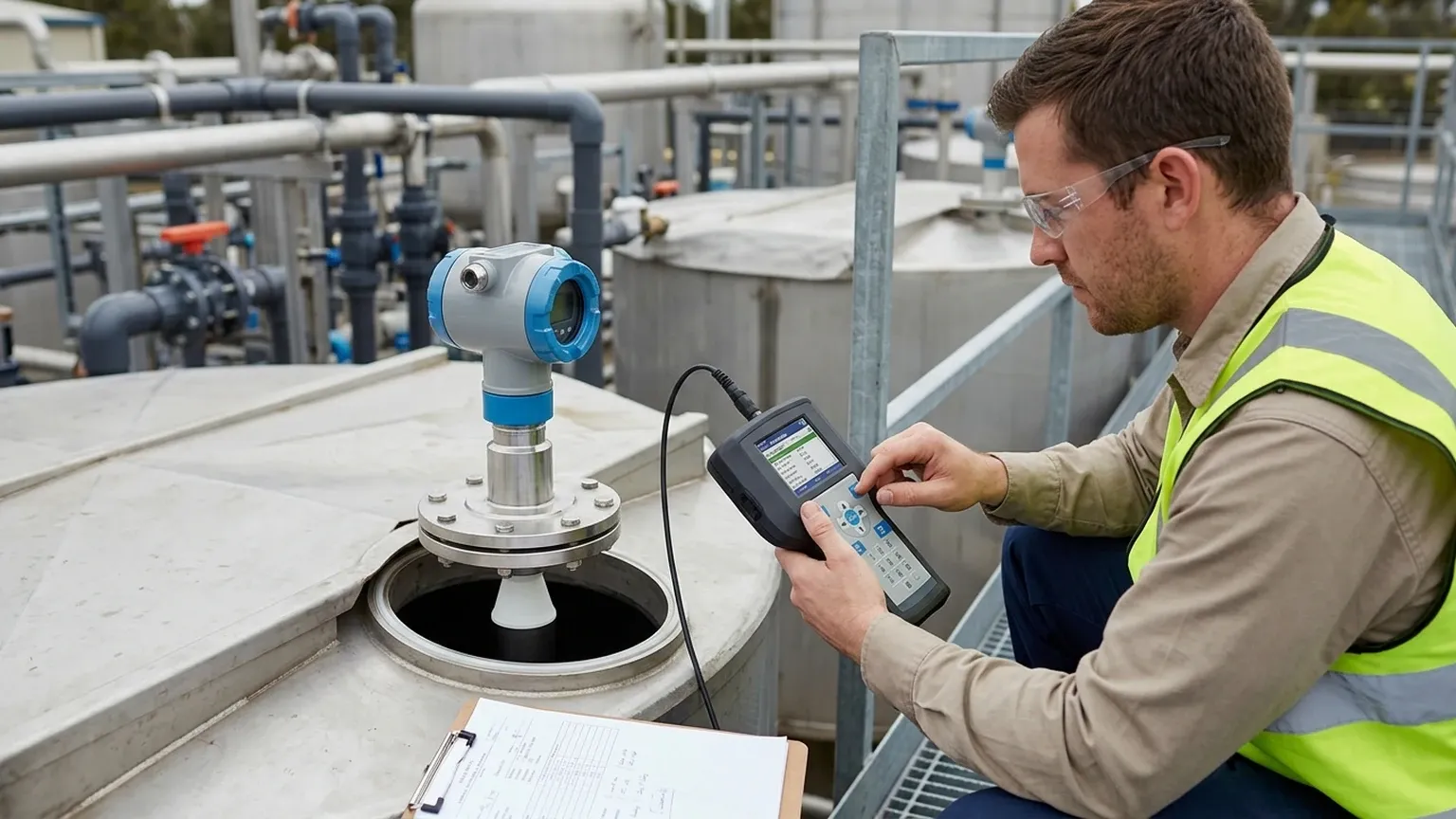
Installation Considerations for Accurate Calibration
Even the most sophisticated calibration cannot compensate for poor installation. To ensure the Ultrasonic Level Meters function correctly, follow these engineering guidelines:
1. Vertical Alignment: The transducer face must be perfectly parallel to the liquid surface. A tilt of even a few degrees can cause the signal to bounce away from the sensor rather than returning to it, resulting in "Loss of Echo" (LOE) errors.
2. Positioning Relative to Inlets: Never install the sensor directly above the filling stream. The turbulence and entrained air will scatter the ultrasonic pulses.
3. The 1/6th Rule: For cylindrical tanks, the ideal mounting position is usually 1/6th of the diameter away from the tank wall. This avoids interference from wall reflections while staying clear of central agitators.
4. Standpipe Usage: If the sensor must be mounted on a tall nozzle, ensure the nozzle is smooth and free of burrs. In some cases, a bypass pipe or stilling well is required to provide a clean path for the signal, especially in foaming applications.
Limitations and Prohibitions
While ultrasonic technology is versatile, it has defined factual boundaries where calibration becomes difficult or impossible:
* Vacuum Applications: Sound cannot travel through a vacuum. Ultrasonic sensors will not work in vessels under full vacuum.
* High Pressure: In high-pressure environments (typically > 3 bar), the density of the gas changes significantly, which can lead to large measurement errors that standard temperature compensation cannot fix.
* Extreme Temperatures: If the process temperature exceeds the rating of the transducer (usually 80°C to 100°C), the piezoelectric crystals may be damaged, and the speed-of-sound calculations become highly unstable.
* Heavy Foam: While light foam can be managed, thick, dense foam (like shaving cream) absorbs the acoustic energy entirely, leading to signal loss.
Frequently Asked Questions (FAQ)
How often should I perform the process of calibrating ultrasonic level?
For most stable applications, an annual check is sufficient. However, if the gas composition in the tank changes (e.g., switching from air to Nitrogen or CO2), the sensor must be recalibrated immediately because the speed of sound in Nitrogen or CO2 is different from air.
Why does my sensor read "Full" when the tank is empty?
This is a common issue known as "ringing" or "near-end reflection." It usually happens if the sensor is mounted too close to a flat surface or if the nozzle is too narrow. The sensor interprets the vibration of the mounting hardware as a return signal. Adjusting the "Near-end Blanking" or dead zone distance can usually resolve this.
Can I calibrate the sensor to ignore an agitator?
Yes. Most professional-grade meters allow for "Gate" or "Window" blanking. You can define a specific distance range (where the agitator blades are located) and instruct the sensor to ignore any echoes originating from that zone, provided the liquid surface echo is stronger.
Does humidity affect the calibration?
Humidity has a minor effect on the speed of sound (less than 0.5% at high temperatures). For most industrial applications, the integrated temperature compensation is sufficient to handle humidity-related variances.
Conclusion
Successful implementation of ultrasonic level measurement depends on a synergy between correct hardware selection, strategic installation, and meticulous calibration. By understanding the Time-of-Flight principle and accounting for environmental variables like temperature and vessel obstructions, engineers can achieve highly accurate and maintenance-free level monitoring.
When calibrating ultrasonic level systems, always refer to the manufacturer’s specific echo profiles and ensure that the "Empty" and "Full" parameters are aligned with the physical constraints of the application. For those seeking robust instrumentation, Welk offers a range of Ultrasonic Level Meters designed to provide reliable performance in the most demanding industrial environments.