Ultrasonic Level Sensor Wiring Diagram
Ultrasonic Level Sensor Wiring Diagram: A Comprehensive Engineering Guide
In industrial process control, the accuracy of liquid and solid level measurement depends as much on the electrical integration as it does on the sensor technology itself. Ultrasonic Level Meters are preferred for their non-contact nature, yet improper installation or an incorrectly interpreted ultrasonic level sensor wiring diagram can lead to signal noise, data loss, or equipment failure.
This guide provides a detailed technical breakdown of wiring configurations, measurement principles, and installation best practices for engineers and technicians working with Welk industrial level instruments.
Understanding the Measurement Principle
Before analyzing an ultrasonic level sensor wiring diagram, it is essential to understand how these devices function. Ultrasonic sensors operate on the "Time of Flight" (ToF) principle.
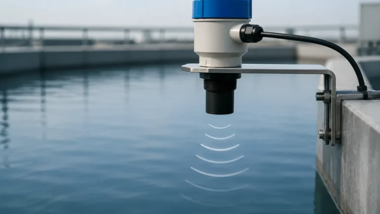
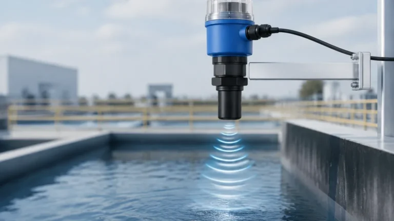
The sensor’s transducer contains a piezoelectric crystal that converts electrical energy into mechanical pulses. These high-frequency sound waves travel through the air to the surface of the medium (liquid or solid), reflect back, and are received by the transducer. The distance is calculated using the formula:
D = (v × t) / 2
* D: Distance to the surface.
* v: Velocity of sound in the air (approximately 343 m/s at 20°C).
* t: Time elapsed between emission and reception.
Because the speed of sound varies with temperature, professional-grade ultrasonic level meters include integrated temperature sensors to compensate for these changes automatically. The resulting distance is then subtracted from the total tank height (the "zero point") to determine the level, which is converted into an analog (4-20mA) or digital (RS485/Modbus) signal.
Common Wiring Configurations
Industrial ultrasonic sensors typically follow one of three wiring architectures. Selecting the correct one depends on the power available at the site and the requirements of the control system (PLC/DCS).
1. 2-Wire (Loop-Powered) Configuration
In a 2-wire setup, the power supply and the signal output share the same pair of wires. The sensor acts as a variable resistor, regulating the current between 4mA (empty) and 20mA (full).
* Advantages: Reduced cabling costs, simpler installation, and suitability for intrinsically safe (Ex-i) environments.
* Power Source: Usually 24V DC provided by the PLC analog input card or an external loop power supply.
2. 3-Wire Configuration
A 3-wire system uses a common ground for both the power supply and the signal output.
* Wiring: One wire for V+ (Power), one for Signal Output (+), and one shared Common/Ground (-).
* Use Case: Often found in budget-friendly applications or where a voltage output (0-10V) is required instead of current.
3. 4-Wire Configuration
In a 4-wire configuration, the power supply circuit is entirely separate from the signal output circuit.
* Wiring: Two wires for power (AC or DC) and two wires for the 4-20mA signal.
* Use Case: Necessary for high-power transducers used in long-range measurements (e.g., 15 meters or more) or when the site only provides AC power (110V/220V).
Technical Analysis: Ultrasonic Level Sensor Wiring Diagram
When reviewing a technical manual, the wiring diagram identifies specific terminal blocks. Below is a representation of the standard terminal assignments for a high-performance Welk ultrasonic transmitter.
Standard Terminal Identification Table
| Terminal Label | Function | Description |
| :— | :— | :— |
| V+ / L | Power Supply (+) | Positive DC input (18-30V) or Line for AC systems. |
| V- / N | Power Supply (-) | Negative DC input or Neutral for AC systems. |
| Out+ / S+ | Signal Output (+) | Positive 4-20mA current loop or RS485 A line. |
| Out- / S- | Signal Output (-) | Negative 4-20mA current loop or RS485 B line. |
| PE / GND | Earth/Shield | Connection for the cable shield to prevent EMI. |
| Relay 1/2 | Alarm Contacts | Optional dry contacts for high/low level switches. |
Wiring for 4-20mA Current Loop (2-Wire)
To wire a 2-wire sensor to a PLC with a sourcing input:
1. Connect the PLC +24V DC output to the sensor's V+ terminal.
2. Connect the sensor's V- terminal to the PLC's Analog Input (+) terminal.
3. Ensure the PLC's Analog Input (-) is jumpered to the power supply common/ground.
Wiring for Digital Communication (RS485/Modbus)
For smart automation systems, digital wiring is required:
1. Connect V+ and V- to a stabilized 24V DC power source.
2. Connect the A and B terminals to the Modbus master gateway.
3. Use a 120-ohm termination resistor at the end of the bus line if the cable run exceeds 100 meters to prevent signal reflection.
Selection Criteria for Wiring and Integration
Choosing the right wiring approach depends on the environmental and technical constraints of the project.
| Feature | 2-Wire (Loop) | 4-Wire (Isolated) | Digital (Modbus) |
| :— | :— | :— | :— |
| Cable Requirement | 1 Shielded Pair | 2 Shielded Pairs | 1 Shielded Pair + Power |
| Max Distance | ~300m (Current loop) | ~500m (Current loop) | ~1200m (RS485) |
| Power Consumption | Low (< 0.5W) | Moderate (2-5W) | Low to Moderate |
| Complexity | Low | Medium | High (Requires Addressing) |
| Noise Immunity | Good | Excellent | Superior |
Critical Installation Considerations
A correct ultrasonic level sensor wiring diagram is only effective if physical installation standards are met. Electrical noise (EMI) is the most common cause of erratic readings in industrial environments.
1. Shielding and Grounding
Always use shielded twisted-pair (STP) cables. The shield should be grounded at one end only—typically at the control cabinet side—to avoid ground loops. Ground loops occur when there is a potential difference between two grounding points, causing current to flow through the shield, which induces noise into the signal wires.
2. Cable Routing
Never run sensor signal cables in the same conduit or cable tray as high-voltage power lines (e.g., 480V motor leads). Maintain a minimum clearance of 300 mm (approx. 12 inches) from AC power cables. If they must cross, do so at a 90-degree angle.
3. Conduit Sealing
In chemical or water treatment plants, humidity can travel through conduits and condense inside the sensor housing, leading to short circuits. Use a certified conduit seal or a "drip loop" in the wiring to ensure moisture drains away from the cable entry point.
4. The "Dead Zone" Awareness
While not strictly a wiring issue, the electrical configuration must account for the sensor's "Dead Zone" (typically 0.25m to 0.5m). The wiring and PLC logic should be programmed to ignore signals within this range to prevent false "Full" tank alarms.
Troubleshooting Common Wiring Issues
If the sensor is powered but providing incorrect or fluctuating data, check the following:
* Weak Current Loop: If the 4-20mA signal never reaches 20mA, check the loop resistance. Most 24V DC loops can handle a maximum resistance of 500-600 ohms. Long cable runs or thin wire gauges (higher than 22 AWG) may increase resistance beyond the sensor's driving capacity.
* Intermittent Signal: Inspect terminal connections for oxidation, especially in wastewater applications. Use ferrules on stranded wire to ensure a secure, vibration-resistant connection.
* Reversed Polarity: Most modern Welk sensors include polarity protection, but reversed wires will result in a 0mA reading or the unit failing to power up.
Frequently Asked Questions (FAQ)
Q: Can I use an unshielded cable for short distances?
A: It is not recommended. Even over short distances, VFDs (Variable Frequency Drives) and large motors can create electromagnetic interference that disrupts the ultrasonic pulse timing.
Q: What is the best wire gauge for ultrasonic level sensors?
A: For most industrial applications, 0.5 mm² to 1.5 mm² (20 to 16 AWG) shielded twisted pair is ideal. This provides a balance between physical strength and low electrical resistance.
Q: Does the wiring change for hazardous areas?
A: Yes. In explosive environments, you must use an intrinsically safe (IS) barrier between the sensor and the PLC. The wiring diagram remains similar, but the power and signal must pass through the barrier to limit energy levels.
Conclusion
Precise level measurement is a cornerstone of industrial automation, and the integrity of the electrical connection is paramount. By following a standardized ultrasonic level sensor wiring diagram and adhering to shielding and routing best practices, engineers can ensure long-term reliability and accuracy.
Whether you are integrating a simple 2-wire loop for water tank monitoring or a complex 4-wire RS485 network for chemical processing, selecting the right instrument is the first step. For detailed specifications on high-accuracy measurement hardware, Review product options and application support to find the solution that fits your specific process requirements.