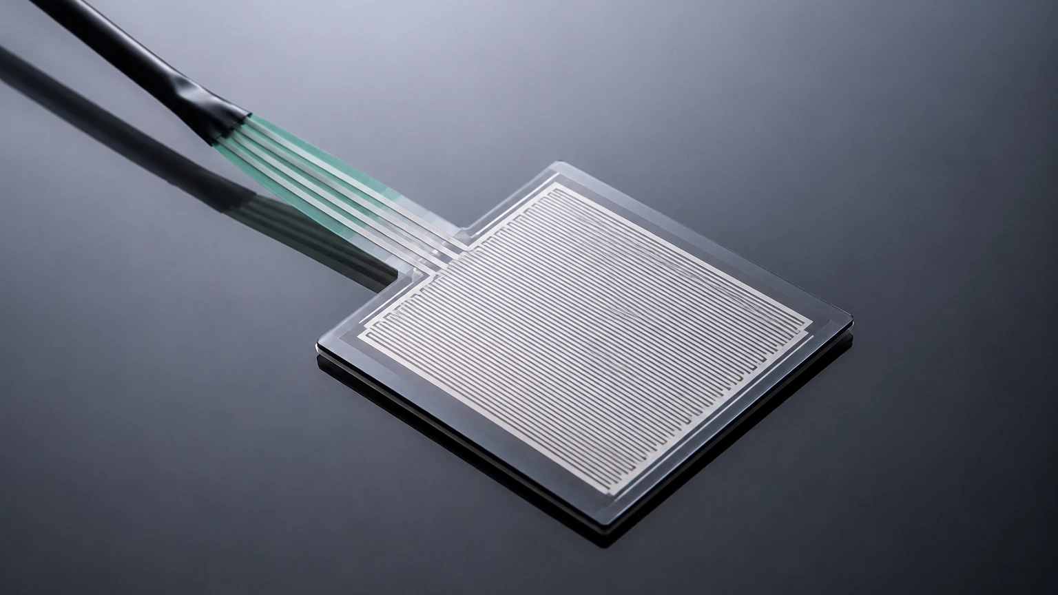
Flat Pressure Sensor
Flat Pressure Sensor
In industrial process control, pressure measurement is a fundamental requirement for monitoring system health, ensuring safety, and managing inventory. However, standard pressure transmitters often feature a recessed diaphragm design where the sensing element is tucked behind a narrow pressure port. While effective for clean gases and liquids, this design fails in applications involving viscous fluids, slurries, or media that crystallize. The flat pressure sensor, often referred to as a flush diaphragm pressure transmitter, is engineered specifically to overcome these challenges by placing the sensing surface directly in contact with the process media without any internal cavities.
Measurement Principles of Flat Pressure Sensors
Before selecting a flat pressure sensor for an industrial application, it is essential to understand the underlying physics that allow these devices to convert physical force into an electrical signal. Most industrial-grade flush sensors utilize one of two primary technologies: piezoresistive or capacitive sensing.
Piezoresistive Sensing Principle
The piezoresistive flat pressure sensor utilizes a silicon or metal diaphragm with integrated strain gauges. When process pressure is applied to the flush face, the diaphragm deflects slightly. This mechanical deformation changes the electrical resistance of the strain gauges, which are typically arranged in a Wheatstone bridge circuit. The resulting change in voltage is proportional to the applied pressure.
In a flat configuration, the sensing element is usually protected by a thin, flexible stainless steel (316L) or Hastelloy diaphragm. A small volume of transmission fluid, such as silicone oil or food-grade vegetable oil, transfers the pressure from the outer flush diaphragm to the internal sensing chip. This design ensures that the sensor remains isolated from harsh chemicals while maintaining a completely flat profile.
Ceramic Capacitive Sensing Principle
Capacitive sensors operate by measuring changes in electrical capacitance between a moving diaphragm and a fixed backplate. In a flat pressure sensor utilizing ceramic technology, the flush face is made of a high-purity alumina (Al2O3) ceramic. As pressure pushes against the ceramic diaphragm, the distance between the electrodes decreases, increasing the capacitance.
Ceramic capacitive sensors are highly valued in the chemical industry because they do not require internal fill fluids, eliminating the risk of process contamination if the diaphragm is breached. Furthermore, ceramic is naturally more resistant to abrasion and corrosion than most metals.
Why Use a Flat Pressure Sensor?
The primary advantage of the flat pressure sensor is the elimination of the "dead space" or pressure port found in traditional sensors. In industries such as wastewater treatment or paper manufacturing, media containing fibers or solids can easily clog a standard pressure port, leading to inaccurate readings or total sensor failure.
Similarly, in food and beverage production, recessed areas can trap bacteria or old product, making Clean-in-Place (CIP) or Sterilization-in-Place (SIP) processes ineffective. The flush design of a flat pressure sensor allows the media to flow freely across the sensing face, ensuring that no residue remains. For engineers looking for reliable solutions in these environments, exploring the Main Page of specialized manufacturers like Welk provides access to a variety of flush-mount configurations designed for these specific challenges.
Technical Selection Criteria
Selecting the correct flat pressure sensor requires a detailed analysis of the process conditions. Because the diaphragm is exposed directly to the flow, it is more vulnerable to mechanical damage and temperature fluctuations than recessed designs.
1. Media Compatibility
The material of the flush diaphragm must be chemically compatible with the process fluid. While 316L stainless steel is the standard, aggressive media may require:
* Hastelloy C: For high-acid environments.
* Tantalum: For extreme chemical resistance.
* PTFE Coating: To prevent sticky substances (like adhesives or latex) from adhering to the sensor face.
2. Pressure Range and Overpressure
Flat sensors are available for ranges as low as 0–100 mbar (10 kPa) up to 0–600 bar (60 MPa). It is critical to account for pressure spikes or "water hammer" effects. Piezoresistive sensors are generally more sensitive to overpressure than ceramic capacitive sensors, which can often withstand 10x to 40x their rated pressure.
3. Temperature Considerations
Process temperature affects the density of the internal fill fluid in metallic flat sensors, which can cause a "zero shift" or thermal drift. If the process operates at high temperatures (e.g., >100°C), a cooling neck or capillary system may be required to protect the electronics.
Selection Table: Flat vs. Recessed Pressure Sensors
| Feature | Flat Pressure Sensor (Flush) | Standard Pressure Sensor (Recessed) |
| :— | :— | :— |
| Best For | Viscous fluids, slurries, food/pharma | Clean liquids, gases, steam |
| Clogging Risk | Extremely Low | High in particulate-heavy media |
| Cleaning | Easy (CIP/SIP compatible) | Difficult; requires disassembly |
| Diaphragm Protection | Exposed; vulnerable to impact | Protected by housing |
| Accuracy | 0.1% to 0.5% FS | 0.05% to 0.25% FS |
| Typical Connections | G1/2", G1", Flange, Tri-Clamp | 1/4" NPT, 1/2" NPT |
Installation Best Practices
Correct installation is paramount for the longevity of a flat pressure sensor. Unlike standard sensors that can be mounted via a simple pipe nipple, flush sensors require specific mounting sockets or weld-on bosses to ensure the diaphragm sits perfectly flush with the inner wall of the pipe or tank.
1. Avoid Mechanical Stress: When tightening a threaded flat pressure sensor, always use the hexagonal flats provided on the body. Never apply torque to the sensor housing or the diaphragm area itself.
2. Gasket Selection: For hygienic applications, the gasket must be sized correctly so that it does not protrude into the flow path or create a gap where material can collect.
3. Orientation: In horizontal pipes, mount the sensor at the 3 o'clock or 9 o'clock position. Mounting at the bottom (6 o'clock) can lead to sediment buildup, while mounting at the top (12 o'clock) may result in air pockets that interfere with accurate pressure transmission.
4. Welding Precautions: If using a weld-on boss, ensure the welding process is complete and the metal has cooled before installing the sensor. Excessive heat during welding can warp the mounting seat, preventing a proper seal.
Limitations and Risks
While the flat pressure sensor is a problem-solver for difficult media, it has inherent limitations:
* Fragility: The flush diaphragm is typically very thin (often less than 0.1 mm for metallic versions). Dropping the sensor or touching the diaphragm with a tool during installation can permanently damage the calibration or rupture the seal.
* Thermal Expansion: In metallic sensors, the expansion of the fill oil due to temperature changes can create a false pressure reading. This is particularly noticeable in low-pressure ranges (below 1 bar).
* Cost: Due to the complexity of the flush diaphragm assembly and the materials required, these sensors are generally more expensive than standard recessed models.
Maintenance and Troubleshooting
In many applications, a flat pressure sensor is "set and forget," but periodic maintenance ensures long-term accuracy.
* Visual Inspection: Regularly check the diaphragm for signs of pitting, corrosion, or mechanical denting. A dented diaphragm will usually show a significant zero offset.
* Zero-Point Calibration: Over time, the sensor may drift. Most modern transmitters allow for a zero-point adjustment via a local display or HART communication. This should be done when the sensor is at atmospheric pressure and at its normal operating temperature.
* Cleaning: If the sensor is used in a non-CIP environment, clean the diaphragm with a soft cloth and a compatible solvent. Never use sharp metal brushes or high-pressure washers directly on the diaphragm face.
Frequently Asked Questions (FAQ)
Q: Can I use a flat pressure sensor for steam applications?
A: Yes, but it is recommended to use a version with a cooling element or a siphon if the steam temperature exceeds the sensor's rated limit (usually 85°C to 100°C for standard electronics).
Q: What is the difference between a flush diaphragm and a chemical seal?
A: A flat pressure sensor has the flush diaphragm integrated directly into the transmitter body. A chemical seal (or remote seal) uses a capillary tube to connect a flush diaphragm to a standard pressure transmitter located some distance away. Integrated flat sensors are more compact and typically have faster response times.
Q: How do I know if my flat pressure sensor has failed?
A: Common signs include a "frozen" output signal that does not change with pressure, a significant jump in the zero-point reading, or the presence of fill fluid in the process media (indicating a diaphragm rupture).
For engineers and procurement professionals, selecting the right instrumentation is a balance of performance and cost. Manufacturers like Welk offer specialized flat pressure sensor solutions that integrate seamlessly into industrial automation frameworks. By understanding the specific needs of the media—whether it is the viscosity of chocolate, the corrosiveness of wastewater, or the purity required in pharmaceutical manufacturing—users can ensure they select a device that provides accurate data for years of service. For more technical specifications and product comparisons, visiting the Main Page is a recommended next step in the engineering design process.