Fluid Level Measurement
Fluid Level Measurement
In industrial process control, fluid level measurement is a fundamental requirement for ensuring operational efficiency, safety, and inventory accuracy. Whether managing water treatment facilities, chemical processing plants, or oil and gas storage, the ability to monitor the volume and height of liquids within tanks, silos, and open channels is critical. Selecting the appropriate technology requires a deep understanding of the physical principles governing different measurement methods, as well as the specific environmental challenges of the application.
As a professional manufacturer, Welk provides a comprehensive range of industrial level measurement instruments. This guide serves as a practical engineering reference for selecting the right technology for fluid level measurement, covering principles, selection criteria, and installation best practices.
Principles of Fluid Level Measurement Technologies
Before selecting a device, it is essential to understand the physical principles that drive different measurement technologies. These are generally categorized into non-contact and contact-based methods.
Radar Level Measurement
Radar level meters operate on the principle of electromagnetic wave reflection. The device emits a high-frequency signal (typically 26GHz or 80GHz) toward the liquid surface. When the signal hits the fluid, a portion of the energy is reflected back to the sensor. The instrument measures the time-of-flight (ToF) or the frequency shift (FMCW) to calculate the distance to the surface.
* Advantages: Radar is highly versatile because electromagnetic waves are not affected by air temperature, pressure, or vacuum. It is ideal for high-temperature applications (up to 400°C) and high-pressure environments (up to 160 bar).
* Considerations: The dielectric constant (εr) of the fluid is a critical factor. Fluids with low dielectric constants (such as certain oils) reflect less energy, requiring more sensitive radar units or guided wave radar (GWR) configurations.
Ultrasonic Level Measurement
Ultrasonic sensors utilize sound waves to determine the fluid level. The sensor emits an ultrasonic pulse that travels through the air, reflects off the liquid surface, and returns to the transducer. The distance is calculated based on the speed of sound.
* Advantages: This is a cost-effective, non-contact solution for standard atmospheric applications, particularly in water and wastewater treatment.
* Considerations: Because sound requires a medium (air) to travel, changes in air temperature, density, and humidity affect accuracy. Most modern ultrasonic sensors include integrated temperature compensation to mitigate these effects. However, they are unsuitable for vacuum applications or environments with heavy foam, which absorbs the acoustic signal.
Hydrostatic Level Measurement
Hydrostatic transmitters measure the pressure exerted by a liquid column at a specific point. The relationship is defined by the formula $P = \rho × g × h$, where $P$ is pressure, $ρ$ is the fluid density, $g$ is gravity, and $h$ is the height of the liquid.
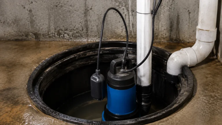
* Advantages: These are highly reliable for deep wells, boreholes, and vented tanks. Submersible pressure transducers are a common choice for groundwater monitoring.
* Considerations: If the tank is pressurized, a differential pressure (DP) transmitter must be used to subtract the head pressure from the total pressure to isolate the liquid level. Accuracy is also dependent on a constant fluid density.
Magnetic Level Gauges
Magnetic level gauges are a contact-based visual measurement solution. They consist of a bypass chamber connected to the vessel. Inside the chamber, a float containing a permanent magnet rises and falls with the liquid level. Outside the chamber, a series of magnetic flags or a follower indicates the level.
* Advantages: They provide a clear visual indication without requiring power, making them excellent for safety-critical applications. They can also be equipped with reed switches or transmitters for remote monitoring.
* Considerations: They are limited by the mechanical movement of the float. High-viscosity fluids or fluids that crystallize can impede float movement.
Key Evaluation Criteria for Fluid Level Measurement
Selecting the right instrument involves more than just choosing a measurement principle; it requires matching the device to the specific process conditions.
1. Fluid Properties: Determine the viscosity, density, and corrosiveness of the liquid. For corrosive chemicals, non-contact radar or PTFE-lined sensors are preferred to prevent material degradation.
2. Process Environment: Evaluate the temperature and pressure ranges. While ultrasonic sensors are limited to roughly 80°C, radar and hydrostatic sensors can handle much more extreme conditions.
3. Vessel Geometry: Internal obstructions such as agitators, heating coils, or ladders can interfere with radar and ultrasonic signals. In such cases, 80GHz radar with a narrow beam angle is often required to bypass these obstacles.
4. Accuracy Requirements: For custody transfer or high-value chemical dosing, high-precision radar (accuracy of ±1mm) may be necessary. For general sump monitoring, an ultrasonic sensor with ±0.25% range accuracy may suffice.
Practical Selection Table
The following table provides a quick reference for comparing common fluid level measurement technologies based on typical industrial performance.
| Technology | Accuracy | Max Temperature | Max Pressure | Best Applications |
| :— | :— | :— | :— | :— |
| 80GHz Radar | ±1 mm | +450°C | 160 bar | Corrosive chemicals, high-pressure reactors, small tanks. |
| Ultrasonic | ±2-5 mm | +80°C | 3 bar | Water treatment, open channels, plastic tanks. |
| Hydrostatic | ±0.1% FS | +100°C | N/A (Submersible) | Deep wells, water reservoirs, vented fuel tanks. |
| Magnetic Gauge | ±5-10 mm | +400°C | 100 bar+ | Boiler drums, oil/water separators, visual monitoring. |
| Level Switch | Point only | +250°C | 64 bar | Overfill protection, pump dry-run prevention. |
Installation Considerations and Best Practices
Even the most advanced fluid level measurement device will fail to provide accurate data if installed incorrectly. Engineers should follow these guidelines during the design and installation phase:
* Dead Zones (Blocking Distance): Both radar and ultrasonic sensors have a "dead zone" immediately below the sensor face where measurement is impossible. Ensure the sensor is mounted high enough so the maximum liquid level never enters this zone.
* Mounting Position: Sensors should be mounted away from the tank inlet to avoid measuring the turbulence of the infilling liquid. For radar and ultrasonic units, the beam should be perpendicular to the liquid surface for maximum signal return.
* Stilling Wells: In tanks with heavy agitation or surface foam, a stilling well (a perforated pipe) can be used to provide a calm surface for the sensor to measure. This is particularly effective for radar and float-based systems.
* Venting: For hydrostatic pressure sensors in vented tanks, ensure the vent tube in the cable is clear and protected from moisture. This allows the sensor to compensate for changes in atmospheric pressure.
Limitations and Potential Risks
Every fluid level measurement technology has inherent limitations that can lead to measurement errors if not properly managed.
* Signal Attenuation: In ultrasonic systems, heavy dust or steam can scatter the sound waves, leading to a "loss of echo." Radar is less susceptible but can still be affected by heavy condensation on the antenna face.
* Density Fluctuations: Hydrostatic measurement assumes a constant fluid density. If the temperature of the liquid changes significantly, the density changes, which will result in an error in the calculated height unless compensated for by a secondary temperature sensor.
* Build-up and Scaling: In wastewater or slurry applications, material can build up on the sensor face or the float of a magnetic gauge. Non-contact sensors are generally better for these environments, but even they may require periodic cleaning if vapors cause crystallization on the antenna.
Frequently Asked Questions (FAQs)
Q: Can I use ultrasonic sensors for measuring fuel level?
A: It is generally not recommended for volatile fuels. Fuel vapors can change the speed of sound in the air space, leading to significant errors. Additionally, fuels often require explosion-proof (Ex-rated) equipment, which is more commonly found in radar or hydrostatic product lines.
Q: What is the difference between 26GHz and 80GHz radar?
A: The primary difference is the beam angle. 80GHz radar has a much narrower beam, allowing it to avoid internal tank obstructions and measure more accurately in small or tall, narrow vessels. 26GHz is often sufficient for larger storage tanks with fewer internal structures.
Q: How do I handle measurement in a tank with heavy foam?
A: Foam is a challenge for both ultrasonic and radar sensors. If the foam is light and airy, radar can often see through it to the liquid surface. If the foam is dense and conductive, it may reflect the signal prematurely. In these cases, a guided wave radar or a hydrostatic transmitter is usually the most reliable solution.
Conclusion
Achieving reliable fluid level measurement requires a balanced approach that considers the physical properties of the media, the mechanical constraints of the vessel, and the environmental conditions of the site. By understanding the principles of radar, ultrasonic, and hydrostatic technologies, engineers can implement solutions that minimize maintenance and maximize process uptime.
For more detailed technical specifications and to explore our full range of industrial instrumentation, you can review product options and application support on the Main Page. Selecting the right instrument today ensures a safer and more efficient process for the future.