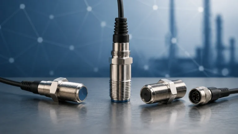
3020-iom-44
3020-iom-44
In the field of industrial process control, the reliability of level measurement instrumentation is directly tied to the precision of its installation and the adherence to technical protocols. The 3020-iom-44 serves as a foundational technical reference—specifically an Installation, Operation, and Maintenance (IOM) framework—for high-performance level transmitters. For engineers and plant operators, understanding the principles outlined in this documentation is essential for ensuring long-term accuracy in demanding environments, from water treatment facilities to complex chemical processing plants.
Welk provides a range of industrial level measurement instruments that align with these rigorous standards. By integrating advanced sensing technologies with robust mechanical designs, these systems provide the data necessary for automation and safety. This guide examines the core measurement principles, selection criteria, and installation requirements associated with the 3020-iom-44 standard.
Core Measurement Principles in Industrial Level Sensing
Before selecting a specific instrument or following the 3020-iom-44 procedures, it is vital to understand the physics behind the measurement. Industrial level meters generally fall into two categories: contact and non-contact. The most common technologies utilized in modern automation include Radar, Ultrasonic, and Hydrostatic sensing.
Time of Flight (ToF) Principle
Both radar and ultrasonic sensors operate on the Time of Flight principle. The sensor emits a signal (either an electromagnetic wave or a sound wave) toward the surface of the medium. The signal reflects off the surface and returns to the sensor. The device calculates the distance ($D$) based on the time delay ($t$) and the speed of the signal ($v$):
$$D = \frac{v \cdot t}{2}$$
In radar applications, high-frequency microwave pulses (often 26GHz or 80GHz) are used. These waves are unaffected by air temperature, pressure, or vacuum, making them ideal for volatile chemical storage. Ultrasonic sensors, conversely, use sound waves and are highly effective for water and wastewater applications where the dielectric constant of the material is not a factor.
Hydrostatic Pressure Principle
Hydrostatic level transmitters measure the pressure exerted by a liquid column. According to Pascal’s law, the pressure ($P$) at the bottom of a tank is proportional to the height of the liquid ($h$), the density of the liquid ($\rho$), and gravity ($g$):
$$P = \rho \cdot g \cdot h$$
This method is widely used in open tanks and deep wells, offering a cost-effective and reliable solution for consistent density liquids. For a deeper dive into these technologies, professionals can visit the Main Page to review specific product specifications and application engineering data.
Technical Specifications and Selection Criteria
Choosing the correct instrument requires an analysis of the process medium and the vessel geometry. The 3020-iom-44 protocol emphasizes that misapplication is the leading cause of instrument failure. The following table provides a comparison of technologies based on typical industrial requirements.
| Feature | Radar Level Meter | Ultrasonic Level Sensor | Hydrostatic Transmitter |
| :— | :— | :— | :— |
| Measurement Range | Up to 120m | Up to 30m | Up to 200m (Cable type) |
| Accuracy | ±1mm to ±3mm | ±0.25% of range | ±0.1% to ±0.5% FS |
| Media Type | Liquids, Solids, Slurries | Liquids, Coarse Solids | Liquids only |
| Process Temp. | -40°C to +450°C | -40°C to +80°C | -20°C to +85°C |
| Process Pressure | Vacuum to 160 bar | Atmospheric | Atmospheric to 40 bar |
| Best Use Case | High-temp chemical reactors | Water tanks, open channels | Deep wells, fuel storage |
Evaluating Dielectric Constants
For radar-based systems mentioned in 3020-iom-44, the dielectric constant ($ε_r$) of the medium is the most critical factor. Materials with low $ε_r$, such as oils or plastic pellets, reflect less energy. In these cases, high-sensitivity antennas or guided wave radar (GWR) may be required to ensure a stable signal return.
Installation Guidelines According to 3020-iom-44
Proper physical placement is the most significant factor in achieving the accuracy rated in the 3020-iom-44 documentation. Even the most advanced Welk radar meter will underperform if installed near a fill stream or an internal agitator.
Nozzle Geometry and Placement
1. Distance from Wall: The sensor should typically be installed at 1/4 to 1/6 of the tank diameter away from the side wall. Installing too close to the wall can cause parasitic reflections that interfere with the true level signal.
2. Nozzle Height: The nozzle should be as short as possible. If a long nozzle is necessary, its internal diameter must be smooth, and the sensor's horn or antenna should ideally extend beyond the bottom of the nozzle to prevent "ringing" or signal dampening.
3. Obstruction Avoidance: The signal beam (usually between 3° and 12° depending on frequency) must have a clear path to the product surface. Internal ladders, heating coils, and agitators must be outside this beam angle.
Wiring and Signal Integrity
Industrial environments are rife with electromagnetic interference (EMI). To maintain signal integrity:
* Use shielded, twisted-pair cables for 4-20mA HART or RS485 Modbus signals.
* Ensure the instrument housing is properly grounded to the vessel or a dedicated plant ground.
* Separate signal cabling from high-voltage power lines by at least 300mm (12 inches).
Operational Calibration and Configuration
Once installed, the device must be configured to the specific dimensions of the vessel. The 3020-iom-44 standard outlines a systematic approach to commissioning:
1. Empty Calibration (Zero Point): Define the distance from the sensor face to the bottom of the tank (0% level). This is often referred to as the "Block Distance" or "Dead Zone" offset.
2. Full Calibration (Span): Define the distance corresponding to the 100% fill level. It is crucial to ensure the 100% level does not enter the sensor’s dead zone (typically the first 100mm to 500mm from the sensor face).
3. False Signal Suppression (Mapping): If there are fixed internal obstructions, the software can "map out" these static reflections. The device records the echo profile of an empty tank and ignores those specific peaks during normal operation.

Maintenance and Troubleshooting Protocols
While Welk instruments are designed for low maintenance, the 3020-iom-44 recommends periodic checks to ensure system health, especially in corrosive or coating-prone applications.
Common Issues and Solutions
* Signal Loss: Often caused by heavy foam on the liquid surface or excessive dust in a silo. Switching to a lower frequency radar or using a stilling well can mitigate this.
* Drifting Readings: Usually a result of temperature-induced density changes in hydrostatic sensors or heavy buildup on an ultrasonic transducer face. Regular cleaning or using a sensor with a self-cleaning flush-mount face is recommended.
* Intermittent Errors: Often traced back to loose wiring terminals or moisture ingress in the housing. Ensure cable glands are tightened to the torque specifications mentioned in the 3020-iom-44.
Limitations of Level Measurement Technologies
No single technology is a universal solution. Engineers must be aware of the following limitations:
* Ultrasonic Sensors: Cannot operate in a vacuum and are sensitive to heavy vapors or wind in outdoor open-channel applications.
* Radar Sensors: While highly versatile, they can struggle with extremely low dielectric materials unless specialized software or GWR is used.
* Hydrostatic Sensors: Are density-dependent. If the liquid density changes (e.g., due to temperature or concentration changes), the level reading will be inaccurate unless compensated by a secondary pressure sensor or a temperature probe.
Frequently Asked Questions (FAQ)
Q: How does the 3020-iom-44 address safety in hazardous areas?
A: The documentation specifies the requirements for Intrinsically Safe (IS) and Explosion-Proof (Ex) wiring. Instruments used in Zone 0 or Zone 1 environments must be installed with appropriate barriers and sealed conduits as per local electrical codes.
Q: Can I use a radar level meter on a plastic tank?
A: Yes. Radar signals can pass through plastic walls. In some cases, the sensor can be mounted outside the tank, looking through the top, provided the plastic is not carbon-filled or metallic-lined.
Q: What is the "Dead Zone" mentioned in the IOM?
A: The Dead Zone (or Blanking Distance) is the area immediately below the sensor where it cannot accurately process a return signal. Any material entering this zone will result in an error or a fixed "full" reading.
Q: How often should a level meter be recalibrated?
A: For non-critical storage, an annual check is sufficient. For custody transfer or high-accuracy chemical dosing, semi-annual or quarterly calibration is recommended to ensure compliance with quality standards.
For further technical support and to explore the full range of instrumentation that meets these industrial standards, please refer to the Main Page for detailed product catalogs and engineering resources.