Digital Fuel Level Sensor
Digital Fuel Level Sensor
In the landscape of industrial automation and fleet management, the transition from traditional mechanical float gauges to the modern digital fuel level sensor represents a significant leap in data precision and operational oversight. For engineers and facility managers, the ability to monitor fuel consumption, detect theft, and optimize refueling schedules depends entirely on the reliability of the underlying sensing technology. Unlike analog sensors that provide a simple variable resistance or voltage, digital sensors process signals internally and transmit data via robust communication protocols, minimizing the impact of electrical noise and signal degradation over long cable runs.
Selecting the appropriate digital fuel level sensor requires an understanding of diverse measurement principles, ranging from contact-based capacitive probes to non-contact ultrasonic transducers. Each technology offers distinct advantages depending on the tank geometry, the chemical properties of the fuel, and the environmental conditions of the installation site.
Understanding Digital Fuel Level Measurement Principles
Before selecting a specific instrument, it is essential to understand how different digital sensors interpret the physical presence of fuel into a data point. Digital sensors typically incorporate an integrated circuit (IC) that performs analog-to-digital (A/D) conversion, signal filtering, and temperature compensation before the data leaves the sensor housing.
Capacitive Measurement Principle
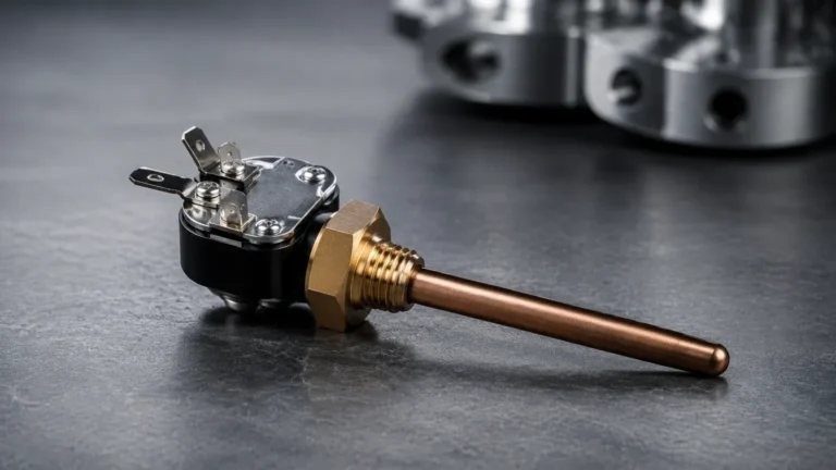
Capacitive digital fuel level sensors operate on the principle of electrical capacitance. The sensor usually consists of two concentric metal tubes that act as electrodes. When the probe is inserted into a tank, the fuel acts as a dielectric material. Since the dielectric constant of fuel (typically between 1.9 and 2.2 for diesel and gasoline) is significantly higher than that of air (approximately 1.0), the total capacitance of the probe changes as the fuel level rises or falls. The internal electronics measure this change and convert it into a digital level reading. This method is highly accurate for consistent fuel types but requires recalibration if the fuel composition changes significantly, such as switching from standard diesel to high-percentage biodiesel.
Ultrasonic Measurement Principle
Ultrasonic sensors utilize the Time-of-Flight (ToF) principle. A transducer mounted at the top of the tank emits a high-frequency sound pulse. This pulse travels through the air, reflects off the surface of the fuel, and returns to the sensor. By measuring the time interval between emission and reception, and knowing the speed of sound in the vapor space, the sensor calculates the distance to the fuel surface. Digital ultrasonic sensors often include sophisticated algorithms to filter out echoes from tank internal structures like baffles or ladders. Because they are non-contact, they are immune to issues like paraffin buildup or mechanical wear.
Hydrostatic Measurement Principle
Hydrostatic sensors measure the pressure exerted by the liquid column above the sensor diaphragm. This pressure is directly proportional to the height of the fuel, following the formula $P = \rho \cdot g \cdot h$, where $\rho$ is the density of the fuel, $g$ is gravity, and $h$ is the height. A digital hydrostatic transmitter converts this pressure into a digital signal. These sensors are often submersible and placed at the bottom of the tank. They are particularly effective for deep storage tanks where long capacitive probes might be impractical to install.
Key Technologies for Digital Fuel Monitoring
When evaluating a digital fuel level sensor, the choice of technology must align with the specific requirements of the application. Industrial manufacturers like Welk provide a range of instruments designed to handle various fuel types and storage conditions. You can review product options and application support on the Welk Main Page.
RS485 and CAN Bus Interfaces
The "digital" aspect of these sensors refers not just to internal processing but to the output interface. Most industrial fuel sensors utilize RS485 (with Modbus RTU protocol) or CAN bus. These interfaces allow for high-resolution data transmission (often up to 0.1 mm resolution) and enable multiple sensors to be daisy-chained on a single bus. This is a critical advantage for sites with multiple storage tanks, as it reduces wiring complexity and allows for centralized monitoring via a PLC or a telematics gateway.
High-Resolution Capacitive Probes
Modern capacitive sensors are often designed with a "cut-to-length" feature, allowing the probe to be adjusted on-site to match the exact height of the tank. This flexibility, combined with digital filtering that eliminates the "sloshing" effect caused by vehicle movement or fuel agitation, makes them the standard choice for mobile fleet tanks and stationary generator sets.
Non-Contact Radar and Ultrasonic Solutions
For fuels that are highly volatile or stored in pressurized vessels, non-contact sensors are preferred. While ultrasonic sensors are cost-effective for standard atmospheric tanks, radar level meters (using 26GHz or 80GHz signals) provide superior performance in environments with heavy vapor or temperature fluctuations, as electromagnetic waves are not affected by the density of the air in the tank's headspace.
Comparison and Selection Criteria
Choosing the right digital fuel level sensor involves balancing accuracy, installation constraints, and budget. The following table provides a general comparison of the primary technologies used in fuel level monitoring.
| Feature | Capacitive Sensor | Ultrasonic Sensor | Hydrostatic Transmitter | Radar Level Meter |
| :— | :— | :— | :— | :— |
| Measurement Type | Contact | Non-contact | Contact (Submerged) | Non-contact |
| Typical Accuracy | ±0.5% to ±1% | ±0.25% to ±0.5% | ±0.25% to ±0.5% | ±1mm to ±3mm |
| Installation | Top-mounted (Probe) | Top-mounted | Bottom or Side | Top-mounted |
| Max Tank Height | ~3000 mm | ~5000 mm | ~20m+ | ~30m+ |
| Fuel Type | Diesel, Gasoline | Most liquids | Most liquids | All fuels/chemicals |
| Maintenance | Low (Clean probe) | Very Low | Low (Check diaphragm) | Minimal |
| Primary Risk | Fuel contamination | Vapor interference | Sediment buildup | High initial cost |
Evaluation Factors
1. Tank Geometry: Tall, narrow tanks may favor hydrostatic sensors, while shallow, wide tanks are better suited for capacitive or ultrasonic sensors.
2. Fuel Stability: If the fuel density or dielectric constant varies frequently (e.g., mixing different grades of fuel), a hydrostatic sensor or a radar meter with density compensation may be required.
3. Environmental Conditions: For outdoor tanks in extreme climates, ensure the sensor has an operating temperature range of at least -40°C to +85°C and an IP67 or IP68 ingress protection rating.
Installation and Calibration Best Practices
The performance of a digital fuel level sensor is heavily dependent on correct installation. Even the most accurate sensor will provide erroneous data if positioned incorrectly or calibrated poorly.
Positioning and Mounting
* Avoid the "Dead Zone": All sensors have a dead zone (blind spot) near the transducer or the top of the probe. Ensure the tank is not filled into this zone, or account for it in the software configuration.
* Central Placement: For ultrasonic and radar sensors, mount the device as close to the center of the tank as possible to avoid reflections from the tank walls. If the tank has internal baffles, the sensor must be positioned so the signal path is clear of these obstructions.
* Verticality: Capacitive probes must be installed perfectly vertical. A tilt of even a few degrees can cause the probe to touch the tank wall (if metal) or lead to inaccurate volume calculations in non-cylindrical tanks.
Calibration Procedures
Digital sensors typically require a two-point calibration: "Empty" and "Full."
1. Empty Calibration: Record the digital value when the tank is at its minimum functional level. This accounts for the unusable fuel at the bottom of the tank (the "unpumpable" volume).
2. Full Calibration: Record the value when the tank is at its maximum safe fill level.
3. Volume Mapping: For irregularly shaped tanks (e.g., horizontal cylindrical tanks), a simple linear calibration is insufficient. A strapping table (calibration chart) must be uploaded to the digital monitoring system to convert the height measurement into an accurate volume (liters or gallons).
Electrical Considerations
Proper grounding is vital for digital sensors, especially in fuel environments where static electricity or lightning strikes pose a safety risk. Use shielded cables for RS485/CAN communication to prevent electromagnetic interference (EMI) from pumps, motors, or vehicle alternators from corrupting the data signal.
Operational Limitations and Environmental Factors
While digital fuel level sensors are highly advanced, they are not without limitations. Understanding these boundaries prevents operational failures and data inaccuracies.
Temperature Effects
Fuel expands and contracts with temperature changes. A digital fuel level sensor measures the *level*, not the *mass*. If a tank is filled with 10,000 liters of diesel at 15°C, and the temperature rises to 35°C, the volume will increase by approximately 160 liters due to thermal expansion. Advanced digital systems integrate a temperature sensor to provide "temperature-compensated volume" readings, which are essential for accurate inventory accounting.
Fuel Foaming and Turbulence
During high-speed refueling, fuel can foam or become turbulent. Ultrasonic sensors may struggle to get a clear reading off a foamy surface, as the foam absorbs the sound pulses. Capacitive sensors are generally less affected by foam but can be influenced by the air bubbles mixed in the fuel. Implementing a software delay or averaging the digital signal over several seconds can help stabilize the output during these events.
Sediment and Paraffin
In diesel storage, paraffin wax can precipitate out of the fuel in cold temperatures and coat the sensor probe or diaphragm. Similarly, sediment can accumulate at the bottom of the tank. Regular maintenance should include inspecting submerged sensors for buildup, which can cause a "drift" in the zero-point calibration over time.
Frequently Asked Questions (FAQ)
Q: Can a digital fuel level sensor detect water at the bottom of the tank?
A: Standard capacitive and ultrasonic sensors measure the top surface of the liquid. However, some specialized digital probes use dual-sensing technology (capacitive and float-based or multi-frequency capacitive) to detect the interface between fuel and water, as water has a much higher dielectric constant (~80) than fuel (~2).
Q: Is it possible to cut a capacitive digital fuel level sensor to fit a shorter tank?
A: Yes, many digital capacitive sensors are designed to be cut to length. After cutting, the sensor must be recalibrated using its digital interface to redefine the new "Full" and "Empty" points.
Q: How does a digital sensor handle tank tilt in mobile applications?
A: In mobile tanks (like those on trucks or heavy machinery), the fuel level is rarely static. Digital sensors use internal firmware to average the readings over time (e.g., a 30-second moving average) to provide a stable level despite the vehicle's movement or inclination. For high-precision requirements, two sensors can be installed at opposite ends of the tank to calculate the true average level.
Q: What is the typical lifespan of an industrial digital fuel sensor?
A: In standard operating conditions, a high-quality digital sensor from a manufacturer like Welk can last 5 to 10 years. The primary factors reducing lifespan are extreme chemical corrosion (if the fuel is contaminated), high-pressure cleaning that damages seals, or electrical surges.
Q: Do digital fuel level sensors require periodic recalibration?
A: While digital sensors are more stable than analog ones, an annual calibration check is recommended. This ensures that any physical changes to the tank (like minor deformations) or the sensor (like film buildup) are accounted for in the monitoring system.
By carefully selecting a digital fuel level sensor based on the measurement principle and environmental requirements, and by following rigorous installation standards, industrial operators can achieve the precision necessary for modern fuel management and cost control.