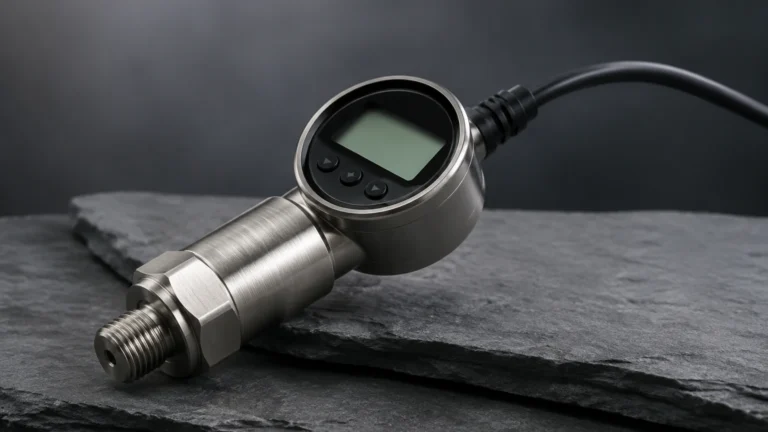
Capacitor Probe
Capacitor Probe
In the field of industrial process control, the capacitor probe remains one of the most versatile and reliable tools for level measurement. Whether monitoring the inventory of a grain silo or controlling the interface of oil and water in a separator, capacitive technology offers a robust solution that can withstand high temperatures, extreme pressures, and chemically aggressive environments. This article provides a detailed engineering reference for understanding, selecting, and installing capacitor probes in industrial applications.
Fundamentals of Capacitance Level Measurement
To effectively implement a capacitor probe, it is essential to understand the underlying physical principles. At its core, the measurement system utilizes the basic principle of an electrical capacitor. A capacitor consists of two conductive plates separated by an insulating material known as a dielectric.
In an industrial level measurement setup, the capacitor probe acts as one electrode, while the vessel wall (if conductive) acts as the second electrode. If the vessel is made of a non-conductive material, such as plastic or fiberglass, a reference rod or a grounded metal strip must be installed to serve as the second electrode.
The capacitance ($C$) of this system is defined by the formula:
$$C = \epsilon_0 \cdot \epsilon_r \cdot (A / d)$$
Where:
* $\epsilon_0$: Permittivity of free space (a constant).
* $\epsilon_r$: Dielectric constant (relative permittivity) of the material between the electrodes.
* $A$: Overlapping area of the electrodes.
* $d$: Distance between the electrodes.
In a level measurement application, $A$ and $d$ are typically fixed by the installation geometry. The variable that changes is the average dielectric constant ($\epsilon_r$) within the vessel. As the process material (liquid or solid) rises, it displaces air or vapor. Since most industrial materials have a higher dielectric constant than air (which has an $\epsilon_r$ of approximately 1.0), the total capacitance increases as the level rises. The electronics in the probe head convert this change in capacitance into a proportional 4-20mA signal or a digital output.
Conductive vs. Non-Conductive Media
The behavior of the capacitor probe changes significantly depending on the conductivity of the medium:
1. Non-Conductive Media (Insulating): For materials like oils, hydrocarbons, or dry powders, the material itself acts as the dielectric. A standard bare metal probe can often be used.
2. Conductive Media: For water-based liquids or acids, the material acts as an extension of the vessel wall electrode. In these cases, the probe must be fully insulated (usually with PTFE or PFA). The insulation material then becomes the dielectric, and the capacitance changes based on how much of the insulated probe is covered by the conductive liquid.
Types of Capacitor Probes and Their Applications
Capacitor probes are manufactured in various configurations to suit different vessel geometries and material characteristics. Choosing the correct physical form is critical for long-term reliability.
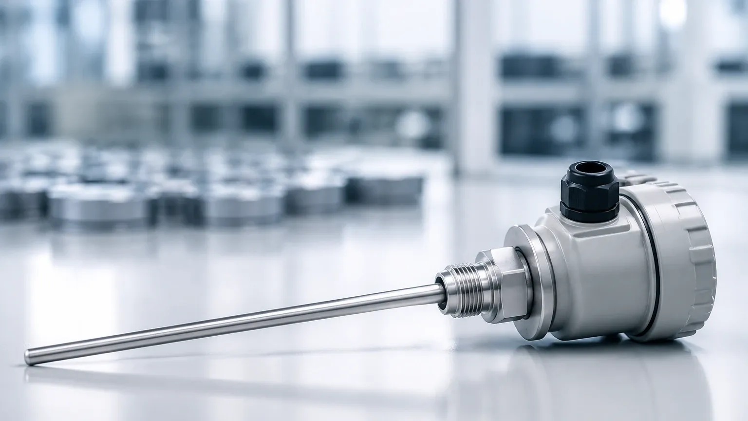
Rod Probes
Rod probes are rigid sensors typically used in smaller vessels or for point-level detection. They are suitable for lengths up to 3 meters (approximately 10 feet). Because of their rigidity, they are ideal for liquids where agitation or turbulence might cause a flexible cable to swing.
Cable Probes
For large silos or deep tanks, cable probes are the preferred choice. These consist of a flexible stainless steel cable, often weighted at the bottom to keep it taut. Cable probes can extend up to 30 meters or more. They are frequently used in the solids industry for measuring bulk materials like cement, plastic pellets, or grain.
RF Admittance Probes
An advanced evolution of the standard capacitor probe is the RF (Radio Frequency) admittance probe. These devices use a high-frequency signal and include a "guard" or "shield" section on the probe. This technology is specifically designed to ignore the effects of material buildup or coating on the probe, which is a common failure point for traditional capacitive sensors in sticky or viscous media.
Selection Criteria for Industrial Capacitor Probes
Selecting the right capacitor probe requires a thorough analysis of the process conditions. Engineers should use the following table as a preliminary guide for technology selection:
| Application Requirement | Recommended Probe Type | Insulation Material | Key Consideration |
| :— | :— | :— | :— |
| Non-conductive liquids (Oil) | Bare Rod or Cable | None / Partial | Low dielectric constant requires high sensitivity. |
| Conductive liquids (Water/Acid) | Insulated Rod | PTFE / PFA | Ensure chemical compatibility of insulation. |
| Bulk Solids (Silos) | Heavy-duty Cable | None (Dry) / PA (Moist) | Account for tensile load on the cable. |
| High Temperature (>200°C) | Ceramic Insulated Rod | Ceramic | Thermal expansion of the probe assembly. |
| High Pressure (>40 bar) | High-pressure Seal Rod | PEEK / Glass-to-Metal | Seal integrity at the process connection. |
| Sticky/Coating Media | RF Admittance Probe | PTFE | Use active shield technology to ignore buildup. |
Dielectric Constant ($\epsilon_r$) Sensitivity
The most important factor is the dielectric constant of the medium. If the $\epsilon_r$ is too low (less than 1.5), standard capacitive measurement may become unstable. In such cases, specialized high-sensitivity electronics or alternative technologies like guided wave radar might be necessary. For a broader look at how these technologies compare, you can review product options and application support on the Main Page.
Installation Guidelines and Best Practices
Correct installation is as important as probe selection. Improper mounting is the leading cause of measurement error in capacitive systems.
1. Grounding and Reference: The measurement depends on a stable reference. In metal tanks, ensure the probe's process connection has a low-resistance electrical contact with the tank. In plastic tanks, a ground rod or a concentric shield (coaxial probe) must be used.
2. Distance from Walls and Obstructions: To maintain a linear output, the capacitor probe should be mounted parallel to the tank wall. Avoid placing the probe near internal structures like ladders, agitators, or heating coils, as these will interfere with the capacitance field.
3. The "Dead Zone": Every probe has an inactive length near the process connection and at the very tip. Ensure that the expected level range falls within the active sensing length of the probe.
4. Mounting Orientation: While vertical mounting is standard for continuous level measurement, point-level capacitor switches can be mounted horizontally. If mounted horizontally, the probe should be angled slightly downward to allow material to shed off, preventing false triggers due to buildup.
5. Cable Tension: For cable probes in solids, the friction of the material pulling on the cable can generate significant downward force. The mounting nozzle and the tank roof must be reinforced to handle these tensile loads.
Challenges and Limitations in Capacitive Sensing
While highly effective, capacitor probes have specific limitations that must be managed:
* Changes in Dielectric Constant: If the composition of the liquid changes (e.g., changing from one chemical to another in a multi-purpose tank), the sensor will require recalibration. Capacitance measurement is not "set and forget" if the medium's properties are fluid.
* Moisture Content in Solids: In bulk solids, a small change in moisture content can drastically change the dielectric constant. This can lead to significant errors in continuous level measurement.
* Vapor Space Condensation: Heavy condensation on the probe insulation can create a conductive path to the tank wall, leading to a false high-level reading. Using an RF admittance probe with a calibrated shield section can mitigate this.
* Temperature Drift: Extreme temperature fluctuations can affect the electronics and the physical dimensions of the probe. High-quality sensors from manufacturers like Welk incorporate temperature compensation to maintain accuracy across a wide operating range.
Maintenance and Troubleshooting FAQ
Q: Why is my capacitor probe reading 100% even when the tank is empty?
A: This is usually caused by a conductive coating or buildup on the probe that creates a short circuit or a high-capacitance path to the ground. Clean the probe or consider upgrading to an RF admittance sensor with an active shield.
Q: Can I use a capacitor probe in a tank with a liner?
A: Yes, but the liner acts as an additional dielectric layer. You will need a reference electrode (like a ground rod) inside the liner, or the system must be calibrated to account for the liner's capacitance.
Q: How often does a capacitor probe need calibration?
A: Calibration should be checked annually or whenever the process material composition changes. For stable, single-product applications, the calibration can remain accurate for several years.
Q: What is the maximum temperature a capacitor probe can handle?
A: With specialized ceramic insulation and heat-dissipating housings, some capacitor probes can operate in environments exceeding 400°C (752°F). Standard PTFE-insulated probes are typically rated up to 200°C (392°F).
Conclusion
The capacitor probe remains a cornerstone of industrial level sensing due to its lack of moving parts and its ability to operate in conditions that would defeat ultrasonic or optical sensors. By accurately matching the probe type to the dielectric properties of the medium and following strict installation protocols, engineers can achieve highly accurate and repeatable measurements. For those seeking to integrate these sensors into modern automation systems, exploring the technical specifications and customized OEM/ODM options available on the Main Page is a recommended next step in the project planning process.