Line Rader
Line Rader
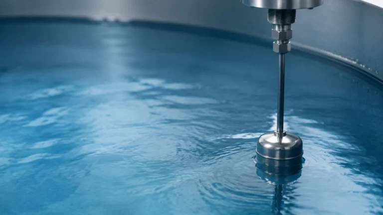
In the landscape of industrial process control, the term "line rader"—frequently used to describe Guided Wave Radar (GWR) or contact-based radar level measurement—represents one of the most reliable technologies for liquid and solid level detection. Unlike non-contact radar systems that broadcast electromagnetic waves through the air, a line rader utilizes a physical waveguide, such as a metal rod or flexible cable, to direct microwave pulses directly to the process medium. This fundamental difference in delivery allows for high-precision measurement in environments where traditional sensors often fail due to foam, turbulence, or complex tank geometries.
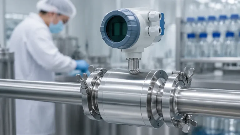
For B2B procurement managers and process engineers, understanding the nuances of line rader technology is essential for optimizing plant efficiency. As a professional manufacturer, Welk provides these advanced industrial level measurement instruments to global markets, ensuring that critical data remains accurate even under extreme pressure and temperature conditions. This guide explores the principles, selection criteria, and installation requirements for line rader systems across diverse industrial sectors.
Measurement Principles of Line Rader Technology
The operational foundation of a line rader is rooted in Time Domain Reflectometry (TDR). The process begins when the sensor’s electronics generate a low-energy, high-frequency microwave pulse. This pulse is launched down the probe (the "line"), which acts as a waveguide.
The Pulse-Echo Sequence
1. Emission: The pulse travels along the probe at the speed of light.
2. Reflection: When the pulse encounters a change in the dielectric constant ($ε_r$)—typically at the surface of the liquid or solid being measured—a portion of the energy is reflected back toward the transmitter.
3. Detection: The sensor’s receiver detects the reflected pulse.
4. Calculation: The internal microprocessor measures the time-of-flight (the time elapsed between emission and reception). Since the speed of the pulse is constant, the distance is calculated using the formula: $D = (c × t) / 2$, where $c$ is the speed of light and $t$ is the measured time.
Because the signal is concentrated along the waveguide, the energy loss is significantly lower than that of non-contact radar. This allows the line rader to measure materials with low dielectric constants or through heavy steam and dust that would otherwise scatter a free-space signal.
Key Advantages in Process Industries
Transitioning to line rader systems offers several distinct advantages over traditional hydrostatic or ultrasonic sensors.
* Immunity to Vapor and Dust: Since the signal is guided, it is unaffected by the atmosphere above the product. This makes it ideal for vacuum tanks or high-pressure boilers.
* Stability in Turbulent Conditions: In tanks with heavy agitation or surface ripples, the waveguide ensures the pulse reaches the surface and returns without being deflected away from the receiver.
* Interface Measurement: One of the unique capabilities of line rader is the ability to measure the interface between two liquids (e.g., oil and water). The pulse reflects off the top layer and a portion continues through to reflect off the second liquid layer.
* No Moving Parts: Unlike float-based magnetic level gauges, the line rader is a solid-state device, reducing mechanical wear and maintenance requirements.
Practical Selection Criteria for Line Rader Systems
Selecting the correct probe configuration is the most critical step in implementing a line rader solution. The choice depends on the viscosity of the medium, the presence of solids, and the dielectric constant of the material.
Probe Types and Their Applications
| Probe Type | Best For | Limitations | Typical Dielectric Range |
| :— | :— | :— | :— |
| Single Rod/Cable | Viscous liquids, slurries, and solids that may cling to the probe. | Most sensitive to electromagnetic interference from tank walls. | ε_r ≥ 10 |
| Twin Rod/Cable | Low dielectric liquids in larger tanks. | Susceptible to bridging if solids or sticky materials are present. | ε_r ≥ 1.9 |
| Coaxial Probe | Clean liquids, turbulent surfaces, and bypass pipes. | Not suitable for viscous media or liquids with particulates. | ε_r ≥ 1.4 |
Material Compatibility
Probes are typically manufactured from 316L stainless steel, but for corrosive chemical applications, coatings such as PTFE (Polytetrafluoroethylene) or PFA are applied. It is vital to confirm that the probe material can withstand the chemical composition of the medium at the maximum operating temperature.
Installation Considerations and Best Practices
To achieve the accuracy specified in the Main Page technical documentation, proper installation is mandatory. Line rader sensors are sensitive to their physical surroundings because the electromagnetic field extends slightly beyond the surface of the probe.
1. Distance from Tank Walls: For single-rod probes, a minimum clearance of 300 mm (approx. 12 inches) from the tank wall is generally required to prevent false reflections. If the tank is made of plastic or concrete, a metal reference plate at the process connection may be necessary.
2. Nozzle Dimensions: The diameter and height of the mounting nozzle can affect the signal. Ensure the nozzle is as short and wide as possible. If a long nozzle is unavoidable, a coaxial probe or a specific nozzle-compensation calibration may be required.
3. Obstructions: Internal structures such as ladders, heating coils, or agitator blades must be kept out of the "signal cone" around the probe.
4. Cable Tensioning: For flexible cable probes used in deep silos (which can reach lengths of 30 meters or more), a weight is attached to the bottom. In some cases, this weight should be anchored to the tank floor to prevent the cable from swinging into the tank wall during filling.

Limitations and Potential Risks
While highly versatile, the line rader is not a universal solution for every application. Engineering teams should be aware of the following constraints:
* Dielectric Minimums: If the material has an extremely low dielectric constant (e.g., certain liquefied gases), the reflection may be too weak to detect. In these cases, a coaxial probe is usually the only viable line rader option.
* Probe Coating and Buildup: While single-rod probes handle buildup better than others, extreme coating of conductive material can attenuate the signal. Regular inspection or the use of "smart" diagnostics that monitor signal strength is recommended.
* Mechanical Stress: In tall silos containing heavy solids (like grain or cement), the lateral forces during discharge can be immense. The probe must be rated for the specific tensile load to prevent it from being pulled out of the mounting flange.
Common Industry Applications
Water and Wastewater Treatment
In this sector, line rader instruments are used for chemical dosing tanks and sludge level monitoring. Their ability to ignore foam makes them superior to ultrasonic sensors in aeration basins.
Chemical and Petrochemical
Line rader is the industry standard for high-pressure storage spheres and distillation columns. The technology's high temperature resistance (up to 400°C in specialized models) allows for continuous monitoring of hot hydrocarbons.
Oil and Gas
In upstream applications, line rader is used for separator tanks where it simultaneously tracks the total level and the oil-water interface, providing two data points from a single process entry point.
Frequently Asked Questions (FAQ)
Q: Can a line rader be used in a non-metallic tank?
A: Yes, but a single-rod probe will require a metal flange or a launch plate to provide a proper reference ground for the microwave pulse. Alternatively, a coaxial probe can be used as it contains the ground within its outer tube.
Q: How does line rader compare to non-contact radar?
A: Non-contact radar is better for extremely corrosive or hygienic applications where you do not want anything touching the product. Line rader is better for low-dielectric products, turbulent surfaces, and applications with heavy foam or steam.
Q: What is the maximum length for a line rader probe?
A: Rigid rod probes are typically limited to 6 meters (approx. 20 feet) due to shipping and installation constraints. Flexible cable probes can extend up to 30 or 70 meters depending on the manufacturer and the tensile strength of the cable.
Q: Does the probe need to be calibrated for different liquids?
A: The primary measurement (level) is based on time-of-flight and does not require recalibration if the liquid changes, provided the dielectric constant remains above the minimum threshold. However, interface measurements do require the dielectric constant of the upper medium to be programmed into the device.
Conclusion
The line rader remains a cornerstone of modern industrial level measurement, offering a blend of precision and ruggedness that few other technologies can match. By guiding the signal directly to the target, it eliminates the variables that often plague free-space measurement systems.
For organizations seeking to upgrade their process automation, selecting a partner with deep technical expertise and a broad product portfolio is essential. Welk continues to lead the industry by providing customized OEM/ODM services and reliable, cost-effective instruments tailored to the specific needs of water treatment, chemical processing, and oil and gas operations. To explore the full range of radar, ultrasonic, and hydrostatic solutions, please visit our Main Page for detailed product specifications and application support.