Electronic Level Sensors
Electronic Level Sensors
In the landscape of modern industrial automation, the ability to monitor and control the volume of liquids and solids within tanks, silos, and processing vessels is fundamental. Electronic level sensors have replaced traditional mechanical methods in most high-stakes environments, providing the precision and data integration necessary for Industry 4.0. These instruments convert physical level changes into standardized electrical signals—such as 4-20mA, HART, or RS485—allowing for real-time monitoring and automated process control.
As a professional manufacturer, Welk provides a comprehensive range of electronic level sensors designed to meet the rigorous demands of water treatment, chemical processing, and the oil and gas industry. Selecting the correct sensor requires a deep understanding of the underlying measurement principles and the specific environmental variables of the application.
Understanding Electronic Level Sensors in Industrial Applications
Electronic level sensors are categorized by their measurement method: point level detection or continuous level measurement. Point level sensors act as switches, triggering an alarm or pump when a specific threshold is reached. Continuous level sensors, however, provide a constant stream of data representing the exact level of the medium at any given time.
For engineers and procurement professionals, the transition to electronic sensing often stems from a need for higher accuracy, reduced maintenance, and better integration with Programmable Logic Controllers (PLCs). Unlike mechanical floats that are prone to scaling and mechanical failure, many electronic sensors utilize non-contact or solid-state technologies that significantly extend the service life of the instrument.
Core Measurement Principles and Technologies
Before selecting a device, it is essential to understand how different electronic level sensors interact with the target medium. Each technology has specific strengths and physical limitations.
1. Radar Level Measurement (ToF and FMCW)
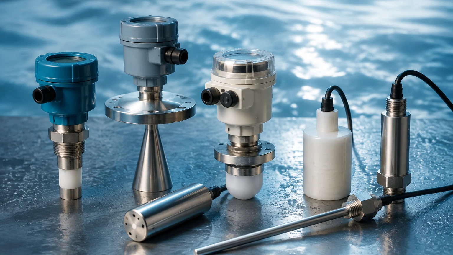
Radar sensors are widely considered the gold standard for high-precision continuous measurement. They work by emitting high-frequency electromagnetic waves (typically in the 26GHz or 80GHz range) toward the product surface. The sensor measures the time it takes for the signal to reflect back.
* Non-Contact Radar: Ideal for corrosive or high-temperature liquids. Since the signal is electromagnetic, it is largely unaffected by vacuum, pressure, or heavy dust.
* Guided Wave Radar (GWR): Uses a probe to guide the signal. This is particularly effective for low dielectric constant (Dk) liquids or applications with heavy foam where a non-contact signal might scatter.
2. Ultrasonic Level Sensors
Ultrasonic sensors emit high-frequency sound pulses. The sensor calculates the distance based on the time of flight of the sound wave. While cost-effective, these sensors are sensitive to the medium through which the sound travels. Changes in air temperature, heavy vapor, or high pressure can alter the speed of sound, leading to measurement errors unless the device includes advanced temperature compensation.
3. Hydrostatic Level Transmitters
Hydrostatic measurement is based on the principle that the pressure at the bottom of a liquid column is directly proportional to the height of the liquid. The formula used is $P = \rho \cdot g \cdot h$, where $P$ is pressure, $\rho$ is the density of the liquid, $g$ is gravity, and $h$ is the height. These sensors are often submersible or mounted to the bottom of the tank via a flange. They are highly reliable for water and wastewater applications where the liquid density remains constant.
4. Magnetic Level Gauges with Electronic Transmitters
For high-pressure and high-temperature visual monitoring, magnetic level gauges are used. By adding a reed chain or magnetostrictive transmitter to the outside of the gauge chamber, the visual indication is converted into an electronic signal. This provides a dual-layer of safety: a local visual check and a remote electronic feed.
Comparative Selection Guide for Electronic Level Sensors
Choosing the right sensor involves balancing performance requirements with budgetary constraints. The following table provides a general comparison of the most common electronic level sensors used in industrial process control.
| Technology | Typical Accuracy | Max Range | Best Use Case | Limitations |
| :— | :— | :— | :— | :— |
| 80GHz Radar | ±1 mm | 120 m | High-precision chemical/oil storage | High initial cost |
| Ultrasonic | ±0.25% of range | 15–30 m | Water tanks, open channels | Sensitive to foam and steam |
| Hydrostatic | ±0.1% to 0.5% | 200 m (H2O) | Deep wells, vented tanks | Affected by density changes |
| Guided Wave Radar | ±2 mm | 30 m | Small tanks with internal obstacles | Probe must be compatible with medium |
| Capacitive | ±1% | 20 m | High-temp solids or liquids | Requires calibration for different media |
When evaluating these options, users are encouraged to Review product options and application support to ensure the selected hardware aligns with their specific chemical compatibility and pressure ratings.
Critical Installation and Engineering Considerations
Even the most advanced electronic level sensors will fail to perform if installation guidelines are ignored. Engineers must account for several physical factors during the design phase.
The "Dead Zone" or Blind Spot
Every top-mounted sensor (Radar and Ultrasonic) has a "dead zone" directly beneath the sensor face where measurement is impossible. If the liquid level rises into this zone, the sensor may report a full tank or an error signal. Typically, this zone ranges from 50 mm to 500 mm depending on the frequency and transducer design. Mounting the sensor on a nozzle that is too tall can also create interference within this zone.
Beam Angle and Internal Obstructions
The signal emitted by radar and ultrasonic sensors spreads out in a cone. If this beam hits tank walls, agitators, or heating coils, it will create "false echoes."
* 80GHz Radar offers a very narrow beam angle (often as low as 3°), making it easier to install in narrow tanks or vessels with internal structures.
* Ultrasonic beams are wider (typically 10° to 12°), requiring more clearance from the tank walls.
Mounting Orientation
Sensors must be mounted perpendicular to the liquid surface to ensure the maximum signal strength is reflected back to the receiver. In silos containing solids, which may form a conical heap, aiming flanges or swiveling holders are often required to align the sensor with the slope of the material.
Managing Operational Risks and Limitations
While electronic level sensors are highly reliable, certain process conditions present risks that must be mitigated through proper device selection.
1. Foam and Turbulence: Thick foam can absorb ultrasonic and radar signals. In such cases, Guided Wave Radar or Hydrostatic transmitters are preferred as they are less affected by surface conditions.
2. Vapor and Condensation: In chemical tanks, condensation can form on the sensor face. Welk radar sensors often utilize PTFE lenses or specialized antenna designs that allow droplets to run off, preventing signal attenuation.
3. Chemical Compatibility: The wetted parts of the sensor—the parts that touch the liquid or gas—must be resistant to corrosion. Common materials include 316L stainless steel, PP, PVDF, and PTFE. For hydrostatic sensors, the cable material (such as PUR or FEP) is just as important as the sensor body.
4. Ambient Temperature and Pressure: Electronic components have specific operating temperature ranges. In extreme heat, remote-mounted electronics or cooling fins may be necessary to protect the transmitter circuitry.
Frequently Asked Questions (FAQ)
Q: Can electronic level sensors measure both liquids and solids?
A: Yes. Radar and ultrasonic technologies are capable of measuring both. However, solids measurement often requires higher-power signals (like 80GHz radar) to account for the uneven surface and lower reflectivity of materials like grain, plastic pellets, or cement.
Q: How do I handle density changes in hydrostatic level measurement?
A: If the density of the liquid changes (e.g., due to temperature fluctuations or mixing different chemicals), the hydrostatic pressure will change even if the level remains the same. In these instances, a differential pressure transmitter or a radar sensor is a more reliable choice.
Q: Is it necessary to calibrate electronic level sensors frequently?
A: Most modern radar and ultrasonic sensors are factory-calibrated and do not drift over time. However, hydrostatic and capacitive sensors may require periodic zero-point checks or re-calibration if the medium properties change.
Q: What is the benefit of a 4-20mA HART signal?
A: The 4-20mA signal provides the level measurement, while the HART (Highway Addressable Remote Transducer) protocol allows for digital communication over the same wires. This enables remote diagnostics, configuration, and the transmission of secondary variables like internal sensor temperature.
Conclusion
The implementation of electronic level sensors is a critical step in optimizing industrial processes. By moving away from manual or mechanical measurement, facilities can achieve higher accuracy, improve safety by preventing overflows, and reduce long-term maintenance costs. Whether the application involves the aggressive chemicals of a processing plant or the clear water of a municipal reservoir, there is a specific electronic sensing technology designed to handle the task.
For technical specifications and assistance in selecting the right instrument for your facility, you can explore the comprehensive resources available on the Main Page of our technical reference site. Proper selection, paired with an understanding of the measurement physics, ensures that your level control system remains a reliable asset for years to come.