Water Tank Level Control System
Water Tank Level Control System
In industrial environments, a water tank level control system is more than a simple mechanism to prevent overflow; it is a critical component of process stability, safety, and resource management. Whether managing cooling water for a power plant, deionized water for pharmaceutical manufacturing, or wastewater treatment buffers, precise level control ensures that downstream processes receive a consistent supply while protecting upstream equipment from dry-running or over-pressurization.
A comprehensive water tank level control system integrates sensing technology, control logic, and final control elements (such as pumps or valves) into a cohesive loop. To design or select the right system, engineers must first understand the physics of the measurement technologies available and how they interact with the specific requirements of the application.
Core Measurement Principles for Water Level Control
Before implementing a control strategy, the method of level detection must be established. Industrial level measurement generally falls into two categories: continuous measurement and point level detection. For a robust water tank level control system, continuous measurement is typically preferred as it allows for sophisticated control logic like PID (Proportional-Integral-Derivative) tuning.
1. Ultrasonic Level Measurement (Non-Contact)
Ultrasonic sensors operate on the Time-of-Flight (ToF) principle. The sensor emits a high-frequency sound pulse that travels through the air, reflects off the water surface, and returns to the transducer. The system calculates the distance based on the speed of sound.
- Advantages: No contact with the medium, low maintenance, and cost-effective for standard water tanks.
- Limitations: Performance can be affected by heavy foam, steam, or extreme turbulence which scatters the sound waves.
2. Radar Level Measurement (Non-Contact)
Similar to ultrasonic, radar uses ToF but employs high-frequency electromagnetic waves (typically 26GHz or 80GHz). These waves are unaffected by air temperature, pressure, or vapor layers.
- Advantages: Extremely high precision (up to ±1mm), works in vacuum or high-pressure environments, and ignores steam or dust.
- Limitations: Higher initial capital expenditure compared to ultrasonic or hydrostatic methods.
3. Hydrostatic Pressure Measurement (Contact)
This method relies on the principle that the pressure at the bottom of a tank is directly proportional to the height of the liquid column above it ($P = \rho gh$). A pressure transmitter is installed at the bottom or submerged in the tank.
- Advantages: Simple installation, highly reliable for vented tanks, and unaffected by surface foam or internal tank obstructions.
- Limitations: Accuracy depends on constant liquid density; if the water temperature or salinity changes significantly, the level reading may drift.
4. Magnetic Level Gauges and Transmitters (Contact)
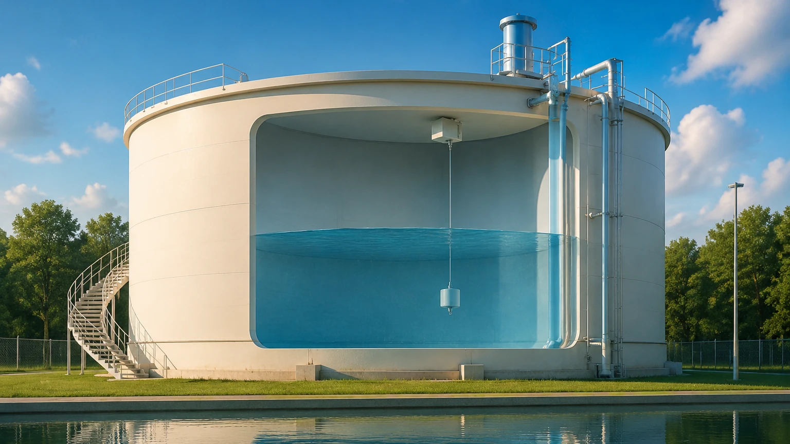
These systems use a float containing a magnet that moves with the water level inside a bypass chamber or directly in the tank. The magnet actuates a visual indicator or a reed-chain transmitter.
- Advantages: Provides a clear visual reference without power and is highly durable in rugged industrial settings.
- Limitations: Mechanical parts are subject to wear or fouling if the water contains high levels of particulates.
Components of an Integrated Control System
A functional water tank level control system consists of three primary layers: the sensor, the controller, and the actuator.
The Sensor Layer
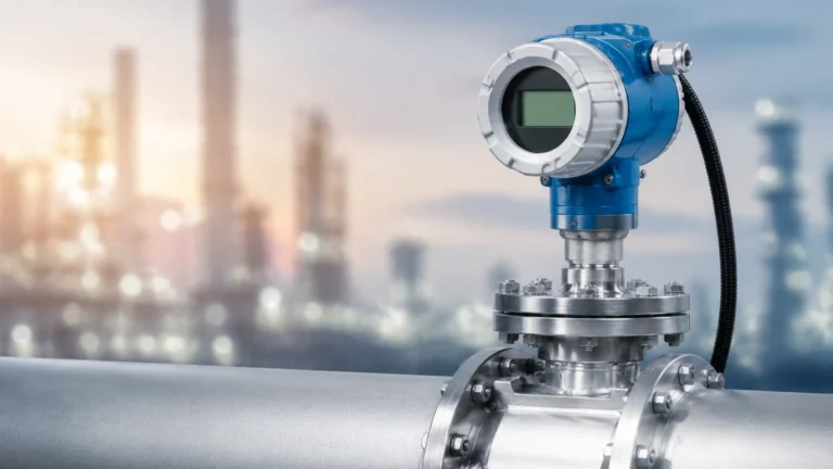
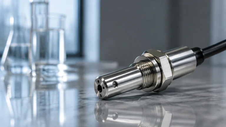
The sensor provides the raw data. In modern B2B applications, sensors often utilize 4-20mA HART, Modbus RS485, or Profibus protocols to communicate with the control layer. For those seeking high-performance hardware, you can Review product options and application support to identify which sensor protocol fits your existing infrastructure.
The Control Layer
This is the "brain" of the system, usually a PLC (Programmable Logic Controller) or a dedicated digital level controller.
- On/Off Control: The simplest form, where a pump starts at a low-level setpoint and stops at a high-level setpoint. This is common in basic sump or storage applications.
- Modulating Control: Uses PID logic to maintain a precise setpoint. For example, if the outflow increases, the controller increases the inflow rate proportionally to keep the level constant. This is essential for boiler feed tanks or chemical blending.
The Actuation Layer
This includes the hardware that physically moves the water.
- Solenoid Valves: Used for simple on/off filling.
- Motorized Control Valves: Used for precise flow modulation.
- Variable Frequency Drives (VFDs): Control the speed of the pump motor to match the required flow rate, significantly reducing energy consumption and mechanical wear.
Selection Criteria for Industrial Applications
Choosing the right components for a water tank level control system requires a balance of technical requirements and budget constraints. The following table provides a general comparison of the most common technologies used in industrial water management.
| Technology | Accuracy | Max Range | Media Suitability | Relative Cost |
| :— | :— | :— | :— | :— |
| Ultrasonic | ±0.25% of range | 15 – 30 meters | Clean water, wastewater | Moderate |
| Radar (80GHz) | ±1 mm | 120 meters | All liquids, steam, foam | High |
| Hydrostatic | ±0.1% to 0.5% | 200 meters | Clean water, deep wells | Low to Moderate |
| Magnetic Gauge | ±5 mm to 10 mm | 6 meters | Process water, condensate | Moderate |
| Level Switch | N/A (Point) | N/A | High/Low alarms | Low |
Installation and Engineering Considerations
Proper installation is as critical as the choice of technology. Even the most advanced radar sensor will fail if placed incorrectly.
Mounting and Positioning
For non-contact sensors (Ultrasonic/Radar), the beam must have a clear path to the water surface.
- Avoid the Inlet: Never install a sensor directly above the water inlet pipe. The turbulence and falling water will cause false readings.
- Beam Angle: Ensure the sensor is mounted far enough from the tank wall to prevent signal interference from weld seams or internal ladders. A 100mm (4-inch) clearance is often the minimum, but this varies by sensor beam angle.
- Dead Zone: All ultrasonic and radar sensors have a "dead zone" or "blocking distance" (typically 0.2m to 0.5m) near the transducer face where measurement is impossible. The sensor must be mounted high enough so the maximum water level never enters this zone.
Environmental Factors
In outdoor water tank level control systems, environmental protection is paramount. Sensors should have an IP67 or IP68 rating. In cold climates, hydrostatic sensors must be protected from freezing, and ultrasonic sensors may require sunshades to prevent temperature compensation errors caused by direct sunlight heating the sensor body.
Redundancy and Safety
In critical B2B applications, such as firewater storage or cooling towers, a single sensor is rarely sufficient. Engineering best practices suggest:
1. Primary Continuous Sensor: (e.g., Radar or Hydrostatic) for daily control.
2. Secondary Point Level Switch: (e.g., Tuning fork or Float switch) installed at the absolute high-level limit to provide a hard-wired emergency pump cutoff, independent of the PLC.
Operational Limitations and Troubleshooting
While modern systems are highly reliable, certain conditions can challenge a water tank level control system:
* Foam Accumulation: In wastewater or tanks with chemical additives, foam can absorb ultrasonic signals. Radar or hydrostatic sensors are preferred in these scenarios.
* Vapor and Condensation: High-temperature water tanks (like condensate return tanks) create heavy steam. This can cause condensation on ultrasonic transducer faces, blocking the signal. Radar sensors with PTFE drip-off antennas are designed to mitigate this.
* Density Fluctuations: If a tank is used for mixing different fluids (e.g., water and brine), a hydrostatic sensor will report a change in "level" even if the volume hasn't changed, because the weight of the column has increased. In these cases, non-contact methods are superior.
Maintenance Guidance
To ensure long-term accuracy, a routine maintenance schedule should be implemented:
- Monthly: Check for physical obstructions or buildup on the sensor face or float.
- Quarterly: Verify the 4-20mA signal against a manual dip-tape measurement.
- Annually: Full calibration of the transmitter using a certified master gauge or by performing a full-tank draw-down test.
Frequently Asked Questions (FAQ)
Q: Can I use an ultrasonic sensor for a pressurized water tank?
A: It is not recommended. Changes in pressure alter the density of the air, which changes the speed of sound and leads to significant measurement errors. Radar or hydrostatic sensors are better suited for pressurized vessels.
Q: What is the benefit of 80GHz radar over 26GHz for water tanks?
A: 80GHz radar has a much narrower beam angle. This allows it to be installed in tanks with internal obstructions (like agitators or heating coils) and provides better performance in small tanks or through narrow nozzles.
Q: How do I handle level control in a tank with heavy turbulence?
A: Turbulence can be managed by using a stilling well (a vertical pipe that dampens surface movement) for non-contact sensors, or by using a hydrostatic transmitter which is naturally less sensitive to surface ripples.
Q: Is wireless level control reliable for industrial use?
A: Yes, WirelessHART or LoRaWAN systems are increasingly common for remote water tanks where trenching for cables is cost-prohibitive. However, they require careful battery management and signal strength mapping.
By understanding these technical nuances, facility managers and systems integrators can design a water tank level control system that minimizes downtime and maximizes operational efficiency. For detailed specifications on the hardware mentioned in this guide, visit the Main Page of our product catalog.