Flow Indicator Transmitter
Flow Indicator Transmitter
In the landscape of industrial process control, the ability to monitor fluid movement in real-time is fundamental to operational safety and efficiency. A flow indicator transmitter serves as a dual-purpose instrument, providing both a local visual confirmation of flow and an electronic signal—typically 4-20mA or a digital protocol—sent to a centralized control system. This integration of local and remote monitoring ensures that field operators and control room engineers have access to consistent, high-accuracy data.
While level measurement instruments like those found on the Main Page are critical for inventory management in tanks, the flow indicator transmitter is the primary tool for managing the dynamics of fluid transport through piping networks. Understanding the underlying measurement principles and selection criteria is essential for any engineering project involving water treatment, chemical processing, or oil and gas automation.
Core Measurement Principles of Flow Indicator Transmitters
Before selecting a flow indicator transmitter, it is necessary to understand how these devices interpret physical fluid movement into measurable data. Different technologies are suited for specific fluid types (liquids, gases, or steam) and environmental conditions.
Electromagnetic Principle
Based on Faraday’s Law of Electromagnetic Induction, these transmitters are used for conductive liquids. As a conductive fluid flows through a magnetic field generated by the meter, it creates a voltage proportional to its velocity. This method is highly accurate and does not require moving parts in the flow stream, reducing maintenance requirements.
Ultrasonic Principle
Ultrasonic transmitters typically use either "Transit-Time" or "Doppler" technology. Transit-time meters measure the time difference between signals sent upstream and downstream. Doppler meters rely on the frequency shift of signals reflecting off particles or bubbles in the fluid. These are often non-intrusive and ideal for retrofitting existing pipelines.
Differential Pressure (DP) Principle
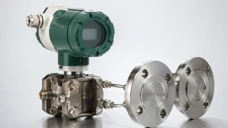
This is one of the most common methods in industrial settings. By placing a primary element (like an orifice plate or Venturi tube) in the pipe, a pressure drop is created. The flow indicator transmitter measures the pressure difference across this element. According to Bernoulli’s equation, the square root of this pressure difference is proportional to the flow rate.
Vortex Shedding Principle
When a fluid encounters a "bluff body" (an obstruction) in the transmitter, it creates alternating vortices. The frequency of these vortices is directly proportional to the flow velocity. This principle is robust and widely used for steam and gas applications where high temperatures are a factor.
Key Components of a Flow Indicator Transmitter
A standard unit is composed of three primary sections:
1. The Sensor/Primary Element: The part in direct contact with the process fluid that detects movement or pressure changes.
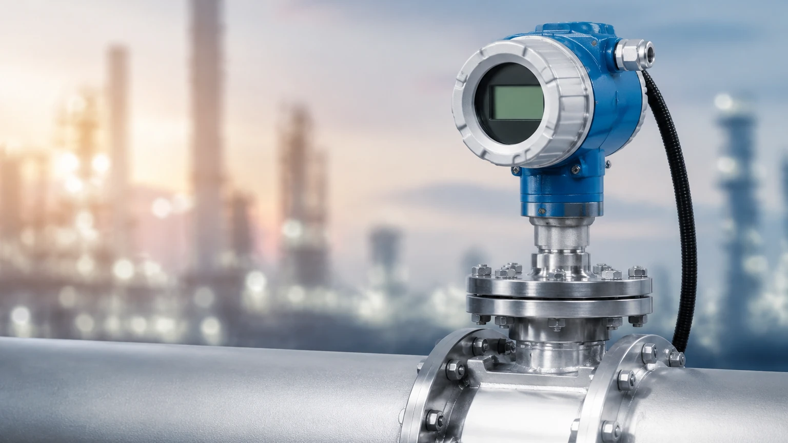
2. The Indicator: A local display, which may be a mechanical dial, a glass viewing window with a flapper/rotor, or a digital LCD screen. This allows for immediate on-site verification.
3. The Transmitter: An electronic module that converts the sensor's physical input into a standard industrial signal (e.g., 4-20mA, HART, Modbus, or Profibus) for transmission to a PLC or SCADA system.
Selection Criteria for Industrial Applications
Choosing the correct flow indicator transmitter requires a detailed analysis of the process environment. Engineers must evaluate the chemical compatibility of the wetted parts, the expected flow range (turn-down ratio), and the physical properties of the fluid.
Comparison Table: Flow Measurement Technologies
| Technology | Fluid Type | Accuracy (Typical) | Pressure Drop | Moving Parts | Best Use Case |
| :— | :— | :— | :— | :— | :— |
| Electromagnetic | Conductive Liquids | ±0.5% | None | No | Water treatment, Slurries |
| Ultrasonic | Clean/Dirty Liquids | ±1.0% | None | No | Large pipes, Non-invasive |
| Differential Pressure| Liquid, Gas, Steam | ±1.0% to ±2.0% | Medium/High | No | High pressure, Steam |
| Vortex | Liquid, Gas, Steam | ±1.0% | Low/Medium | No | High temperature steam |
| Turbine | Clean Liquids | ±0.25% | Medium | Yes | Fuel measurement, High accuracy |
Fluid Properties and Compatibility
* Viscosity: High-viscosity fluids (like heavy oils) may require positive displacement or specialized DP transmitters.
* Conductivity: Electromagnetic transmitters require a minimum conductivity (usually >5 μS/cm).
* Corrosivity: For aggressive chemicals, transmitters must be constructed from materials like PTFE, Hastelloy, or high-grade stainless steel.
Installation and Calibration Best Practices
The accuracy of a flow indicator transmitter is heavily dependent on its installation. Even the most advanced sensor will provide erroneous data if the flow profile is disturbed by turbulence.
Straight Pipe Requirements
To ensure a laminar (stable) flow profile, transmitters usually require a specific length of straight pipe upstream and downstream. A common rule of thumb is "10D upstream and 5D downstream," where D is the nominal pipe diameter. For example, a 100 mm (approx. 4 inches) pipe would require 1000 mm of straight run before the meter and 500 mm after it. If elbows, valves, or pumps are located near the installation point, these requirements may increase.
Orientation and Grounding
* Liquid Applications: The pipe must remain full at all times. Vertical upward flow is often preferred to prevent air pockets.
* Gas Applications: Transmitters should be installed to prevent moisture accumulation in the sensor housing.
* Grounding: For electromagnetic transmitters, proper grounding is critical to eliminate electrical noise that could interfere with the low-voltage signal generated by the sensor.
Calibration Considerations
Industrial transmitters should be calibrated at least once a year. While many modern digital units offer "self-diagnostics," a physical wet-calibration or a comparison against a master meter ensures the instrument remains within its specified tolerance. This is especially important in regulated industries like pharmaceuticals or food and beverage.
Limitations and Operational Risks
While a flow indicator transmitter is a robust tool, it is not without limitations. Engineers must be aware of potential failure points to avoid process downtime.
1. Reynolds Number Constraints: Many flow technologies (like Vortex and DP) require the fluid to be in a turbulent regime (high Reynolds number) to provide accurate readings. In low-flow or high-viscosity scenarios, accuracy may drop significantly.
2. Entrained Air: In liquid flow measurement, the presence of air bubbles can lead to significant over-reading or signal loss, particularly in ultrasonic and electromagnetic meters.
3. Mechanical Wear: For turbine or paddle-wheel indicators, suspended solids can cause abrasion or jamming of the moving parts, leading to mechanical failure.
4. Signal Interference: In environments with heavy machinery, electromagnetic interference (EMI) can distort the 4-20mA signal if shielded cabling is not used correctly.
Integration with Level Measurement Systems
In many B2B industrial projects, flow and level measurement go hand-in-hand. For instance, in an open channel flow application (such as a wastewater flume), a level sensor—like an ultrasonic or radar level meter—is used to measure the height of the liquid. This height is then converted into a flow rate using a standardized formula.
Similarly, in tank farm management, a flow indicator transmitter monitors the rate of filling or discharge, while a magnetic level gauge or radar sensor monitors the total volume remaining. Integrating these two data points allows for "mass balance" calculations, which help detect leaks or discrepancies in the process. For projects requiring comprehensive instrumentation, reviewing the full range of level and flow solutions on the Main Page is recommended to ensure system compatibility.
Frequently Asked Questions (FAQ)
Q: Can a flow indicator transmitter measure bidirectional flow?
A: Yes, certain technologies like electromagnetic and ultrasonic transmitters are inherently capable of measuring flow in both directions, provided the electronics are configured to output a signed signal.
Q: What is the difference between a flow switch and a flow indicator transmitter?
A: A flow switch is a binary device that triggers an alarm when flow reaches a specific set point (On/Off). A transmitter provides a continuous signal representing the actual rate of flow (e.g., 0 to 100 m³/h).
Q: How do I handle high-temperature fluids?
A: For temperatures exceeding 150°C (302°F), remote-mounted electronics or specialized vortex and DP transmitters with cooling fins or impulse lines are required to protect the transmitter's circuitry.
Q: Is it possible to measure flow in a pipe that is only partially full?
A: Standard flow transmitters require a full pipe for accuracy. For partially filled pipes, specialized area-velocity flow meters or level-based flume systems are necessary.
By adhering to these engineering principles and selection guidelines, process managers can ensure that their flow indicator transmitter installations provide the reliable data necessary for optimized industrial automation. For technical support and product specifications, engineers should consult with professional manufacturers to match the instrument to the specific chemical and physical demands of their application.