Ultrasonic Level Sensor How It Works
Ultrasonic Level Sensor How It Works: A Practical Engineering Guide
In the realm of industrial process control, selecting the right instrumentation is critical for operational efficiency and safety. Among the various technologies available, non-contact measurement has become a preferred standard for many liquid and solid applications. Understanding an ultrasonic level sensor how it works is the first step for engineers and plant managers in determining if this technology suits their specific environmental conditions.
As a professional manufacturer, Welk provides a range of Ultrasonic Level Meters designed to handle diverse industrial challenges, from water treatment to chemical storage. This guide explores the underlying physics, technical components, and practical application considerations for these instruments.
The Core Principle: How an Ultrasonic Level Sensor Works
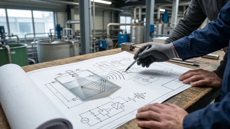
At its most fundamental level, an ultrasonic level sensor operates on the "Time-of-Flight" (ToF) principle. Unlike hydrostatic sensors that measure pressure or float switches that rely on physical contact, ultrasonic devices use sound waves to determine the distance to a material surface.
The Measurement Cycle
1. Emission: The sensor’s transducer contains a piezoelectric crystal. When energized with electrical pulses, this crystal vibrates at a high frequency (typically between 20 kHz and 200 kHz), emitting a burst of ultrasonic sound waves toward the target.
2. Propagation: These sound waves travel through the air or gas medium in the tank at the speed of sound.
3. Reflection: Upon hitting the surface of the liquid or solid medium, the sound waves are reflected back toward the sensor.
4. Detection: The transducer receives the reflected echo and converts the mechanical vibration back into an electrical signal.
5. Calculation: The internal microprocessor measures the time interval between the emission of the pulse and the reception of the echo.
The Mathematical Formula
The distance ($D$) from the sensor to the material surface is calculated using the following formula:
$D = (c \times t) / 2$
Where:
* $c$ is the speed of sound in the medium (approximately 343 m/s in air at 20°C).
* $t$ is the total transit time (the time it takes for the pulse to travel to the surface and back).
Since the total height of the tank ($H$) is a known constant programmed into the device during calibration, the actual level ($L$) of the material is determined by subtracting the measured distance from the total height:
$L = H – D$
Key Components of Ultrasonic Level Meters
To ensure accuracy in industrial environments, these instruments consist of several sophisticated components working in tandem:
* Transducer: The "heart" of the sensor. It acts as both a speaker and a microphone. High-quality transducers are designed to minimize the "ringing" effect, which helps reduce the dead zone.
* Microprocessor and Signal Processing: Modern sensors use advanced algorithms to filter out noise, such as echoes from tank walls, agitators, or ladders. This is often referred to as "False Echo Suppression."
* Temperature Sensor: Because the speed of sound changes with air temperature, most industrial ultrasonic level meters include an integrated temperature probe to provide real-time compensation.
* Output Interface: The measured data is converted into a standard industrial signal, such as 4-20mA, RS485 (Modbus), or HART protocols, for integration into PLC or SCADA systems.
Technical Factors Affecting Accuracy
While the principle is straightforward, several environmental factors can influence the performance of an ultrasonic level sensor. Understanding these is vital for successful implementation.
1. The Speed of Sound and Temperature
Temperature is the most significant variable. In air, the speed of sound changes by approximately 0.6 m/s per degree Celsius. Without compensation, a 10°C (18°F) temperature shift could result in a measurement error of nearly 2%. Industrial-grade sensors mitigate this by measuring the ambient temperature near the transducer.
2. The Blocking Distance (Dead Zone)
Every ultrasonic sensor has a "dead zone" (also known as the blocking distance) directly beneath the transducer face. This is the time required for the piezoelectric crystal to stop vibrating after emitting a pulse before it can listen for the return echo. Typically, this range is between 0.2 meters (0.66 ft) and 0.5 meters (1.64 ft). Material levels must not enter this zone, or the sensor will provide erratic readings.
3. Beam Angle and Spread
The ultrasonic pulse is not a laser beam; it spreads out in a conical shape. The "beam angle" (usually between 5° and 12°) determines how much space the pulse requires. If the beam hits a tank wall or an internal obstruction like a pipe, it will create a false reflection.
Selection Criteria for Industrial Applications
Choosing the right model requires balancing the physical properties of the medium with the tank geometry. Below is a practical selection table for common industrial scenarios.
| Application | Recommended Sensor Type | Key Consideration |
| :— | :— | :— |
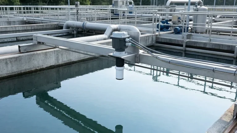
| Open Water Channels | Standard Integrated Type | Requires IP68 rating for outdoor weather resistance. |
| Chemical Storage Tanks | Corrosion-Resistant (PTFE/PVDF) | Transducer material must be compatible with vapors. |
| Small Process Vessels | Narrow Beam Angle (< 6°) | Prevents interference from narrow tank walls. |
| Deep Silos/Sumps | High-Power Long Range | Requires lower frequency (e.g., 20-30 kHz) for distances up to 30m (98 ft). |
| Explosive Environments | Intrinsically Safe (Ex-proof) | Must meet ATEX or IECEx certifications for Zone 0/1. |
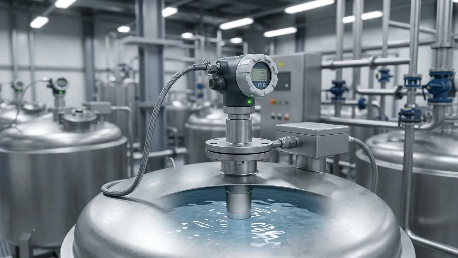
Installation Best Practices
Proper installation is often more important than the sensor's specifications. To ensure reliable data, follow these engineering guidelines:
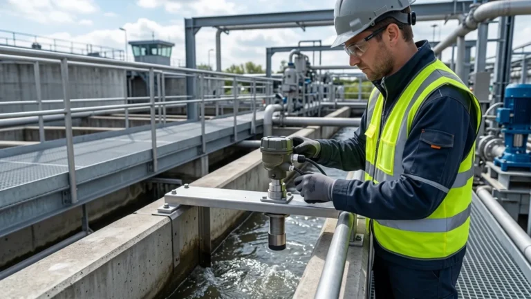
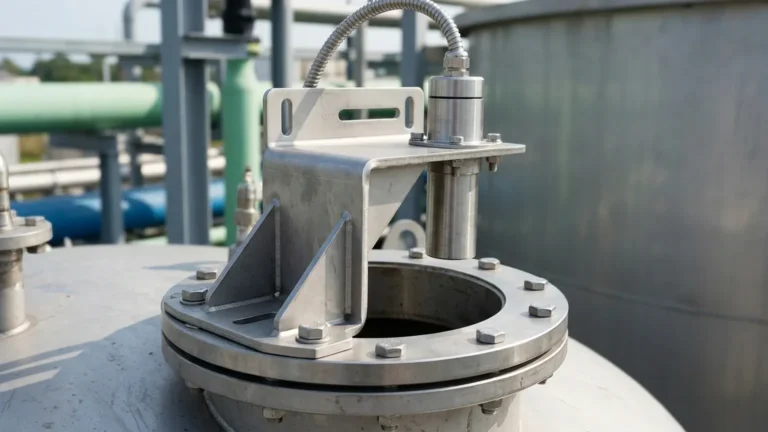
1. Vertical Alignment: The transducer face must be perfectly parallel to the liquid surface. A tilt of even a few degrees can cause the reflected signal to bounce away from the sensor, leading to signal loss.
2. Avoid the Fill Path: Never install the sensor directly above the point where the tank is filled. The turbulence and falling material will interfere with the ultrasonic pulses.
3. Distance from Walls: Maintain a distance from the tank wall at least 1/10th of the total tank height to avoid "ringing" echoes from the sides.
4. Obstruction Clearance: Ensure the beam path is clear of ladders, heating coils, and agitators. If obstructions are unavoidable, use a sensor with software-based false echo masking.
5. Sun Shielding: For outdoor installations, use a sunshade. Direct sunlight can heat the sensor body significantly higher than the actual air temperature, leading to inaccurate temperature compensation.
Limitations and Common Risks
While highly versatile, ultrasonic technology is not a universal solution. Engineers should be aware of the following limitations:
* Foam: Heavy, dense foam on a liquid surface acts as an acoustic absorber. It soaks up the sound pulse rather than reflecting it, causing the sensor to lose the signal.
* Vacuum: Sound waves require a medium (air or gas) to travel. Therefore, ultrasonic sensors cannot work in a vacuum.
* High Pressure/Temperature: Extreme pressures change the density of the gas, affecting the speed of sound beyond the limits of standard compensation. Generally, ultrasonic sensors are limited to pressures below 3 bar (43.5 psi).
* Heavy Dust or Steam: While light dust is manageable, extremely dense dust clouds (common in some grain silos) or heavy steam can attenuate the signal.
Frequently Asked Questions (FAQ)
Can ultrasonic sensors measure solids?
Yes, but with caveats. Solids like powders or grains do not reflect sound as efficiently as liquids. They often form a conical pile which can deflect the signal. For solids, it is recommended to use a sensor with a higher power output and a wider range rating than the actual depth of the silo.
What is the difference between an integrated and a split-type sensor?
An integrated sensor has the transducer and the electronics/display in a single housing. It is easier to install and more cost-effective. A split-type sensor separates the transducer from the controller. This is useful when the measurement point is difficult to access or when the environment at the tank top is too harsh for the display electronics.
How do I handle turbulence in the tank?
If the liquid surface is turbulent due to an agitator, the reflected signal may be scattered. This can be resolved by using the software's "averaging" function to smooth out the readings or by installing a stilling well (a vertical pipe) to provide a calm surface for the sensor to measure.
Does the color of the liquid affect the measurement?
No. Unlike optical or laser sensors, ultrasonic technology is completely unaffected by the color, transparency, or opacity of the medium.
Conclusion
Understanding an ultrasonic level sensor how it works allows for better decision-making during the plant design and maintenance phases. By leveraging the Time-of-Flight principle, these sensors provide a reliable, low-maintenance solution for a vast array of industrial level monitoring needs. For applications involving corrosive chemicals, wastewater, or standard tank storage, Ultrasonic Level Meters offer a balance of accuracy and cost-effectiveness that is difficult to match with contact-based methods.
When specifying a sensor, always confirm the chemical compatibility of the transducer, the required measurement range, and the presence of any environmental factors like foam or high vapor concentrations that might necessitate a specialized solution.