Ultrasonic Level Measurement Working Principle
Ultrasonic Level Measurement Working Principle: A Comprehensive Engineering Guide
In the field of industrial automation, selecting the right level measurement technology is critical for process efficiency, safety, and inventory management. Among the various technologies available, ultrasonic level measurement has emerged as one of the most versatile and cost-effective solutions for liquid and solid monitoring. This guide provides a detailed technical analysis of the ultrasonic level measurement working principle, selection criteria, and practical installation strategies for engineering professionals.
Understanding the Ultrasonic Level Measurement Working Principle
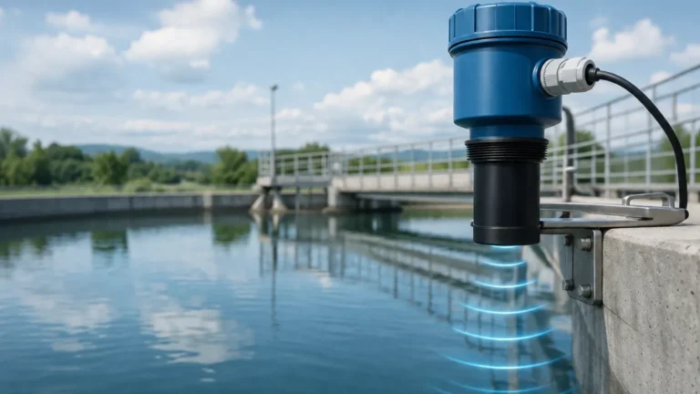
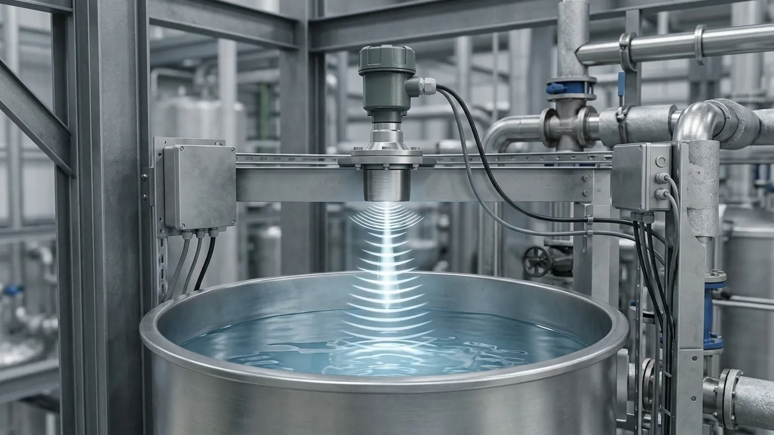
The fundamental ultrasonic level measurement working principle is based on the "Time of Flight" (ToF) technology. This method utilizes high-frequency sound waves—well above the range of human hearing—to determine the distance between a sensor and the surface of a target medium.
The Measurement Cycle
An ultrasonic level meter consists of a transducer containing a piezoelectric crystal. The measurement process follows a repetitive cycle:
1. Emission: The electronic circuit triggers the piezoelectric crystal to vibrate at a specific frequency (typically between 20 kHz and 200 kHz). This creates a pulse of ultrasonic energy that is directed toward the target.
2. Propagation: The sound pulse travels through the air or gas space in the vessel at the speed of sound.
3. Reflection: Upon reaching the surface of the medium (liquid or solid), a portion of the sound energy is reflected back toward the sensor as an echo.
4. Reception: The transducer receives the reflected echo and converts the mechanical vibration back into an electrical signal.
5. Calculation: The internal microprocessor measures the time interval between the emission of the pulse and the reception of the echo.
The Mathematical Formula
The distance ($D$) from the sensor to the material surface is calculated using the following formula:
$$D = \frac{v \times t}{2}$$
Where:
* $v$ is the speed of sound in the medium (typically air).
* $t$ is the total time elapsed for the pulse to travel to the surface and back.
Since the total distance traveled is twice the distance to the surface (down and back), the result is divided by two. To determine the actual level ($L$) of the material in a tank of height ($H$), the device subtracts the measured distance from the total tank height: $L = H – D$.
The Role of Temperature
The speed of sound is not constant; it fluctuates based on the temperature of the air through which it travels. In air, the speed of sound increases by approximately 0.6 meters per second for every degree Celsius increase in temperature. To maintain accuracy, modern Ultrasonic Level Meters include an integrated temperature sensor to provide real-time compensation for these variations.
—
Key Components of Ultrasonic Level Meters
To implement the ultrasonic level measurement working principle effectively, the instrument incorporates several critical sub-systems:
* Transducer: The "heart" of the meter, responsible for converting electrical energy into sound and vice versa. Welk transducers are designed with specialized materials to resist chemical corrosion and mechanical wear.
* Signal Processing Electronics: Advanced algorithms are used to filter out noise, such as echoes from tank walls, agitators, or internal bracing. This is often referred to as "False Echo Suppression."
* Display and Interface: Most industrial units feature an LCD for local monitoring and provide standard outputs such as 4-20mA, HART, Modbus RS485, or relay switches for automation integration.
—
Technical Selection Criteria
When specifying an ultrasonic level meter, engineers must evaluate several parameters to ensure the device matches the application requirements. The following table provides a general comparison for selection based on typical industrial standards.
Selection Table: Ultrasonic Level Meter Specifications
| Parameter | Standard Range / Value | Engineering Consideration |
| :— | :— | :— |
| Measurement Range | 0.3m to 30m (1ft to 98ft) | Longer ranges require lower frequencies to overcome attenuation. |
| Accuracy | ±0.25% to ±0.5% of Full Scale | Higher precision is available for shorter ranges and stable environments. |
| Beam Angle | 5° to 12° | Narrower beam angles are better for tall, narrow tanks with obstructions. |
| Output Signal | 4-20mA, RS485, Relays | Compatibility with PLC/DCS systems is essential. |
| Operating Temperature | -40°C to +70°C | High-temperature versions are required for steam-heavy processes. |
| Process Pressure | Up to 0.3 MPa (3 bar) | Ultrasonic sensors are generally not suitable for high-pressure vessels. |
| Protection Rating | IP66, IP67, or IP68 | Essential for outdoor or wash-down environments. |
—
Installation Considerations and Best Practices
Correct installation is as important as the ultrasonic level measurement working principle itself. Even the most advanced sensor will fail if positioned incorrectly.
1. The Dead Zone (Blocking Distance)
Every ultrasonic sensor has a "Dead Zone" directly beneath the transducer face, typically ranging from 0.2m to 0.6m depending on the frequency. In this zone, the transducer cannot switch from "transmit" to "receive" mode fast enough to capture the echo. The sensor must be mounted high enough so that the maximum liquid level never enters this dead zone.
2. Beam Angle and Obstructions
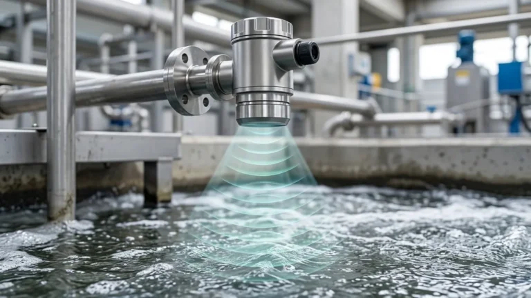
The ultrasonic pulse spreads in a cone shape. Any internal structures (ladders, pipes, heating coils) within this cone will create false echoes.
* Rule of Thumb: Maintain a distance from the tank wall of at least 1/10th of the tank height to avoid wall interference.
* Orientation: The transducer face must be perfectly parallel to the liquid surface to ensure the echo returns directly to the sensor.
3. Avoiding Turbulence and Fill Streams
Do not install the sensor directly over the inlet pipe. Falling liquid creates turbulence and air bubbles that scatter the ultrasonic signal, leading to erratic readings. If turbulence is unavoidable, a stilling well (a vertical pipe) can be used to provide a calm surface for measurement.
—
Limitations and Common Risks
While highly effective, the ultrasonic level measurement working principle has physical limitations that must be acknowledged during the design phase:
* Vacuum Conditions: Sound requires a medium to travel. In a vacuum, ultrasonic waves cannot propagate, making these meters unusable.
* Heavy Foam: Foam on the surface of a liquid acts as an acoustic absorber. Light, airy foam may allow measurement, but thick, dense foam will often absorb the signal entirely, resulting in a "Loss of Echo" error.
* Dust and Vapor: Extremely high concentrations of dust or heavy steam can attenuate the sound pulse. In such cases, high-power transducers or radar-based level meters may be more appropriate.
* Surface Turbulence: Rapidly boiling or agitated liquids can scatter the signal. Signal averaging and damping settings in the electronics can mitigate minor turbulence.
—
Frequently Asked Questions (FAQs)
Q1: Can ultrasonic level meters be used for solids like grain or sand?
Yes, but with caveats. Solid surfaces are often uneven and angled, which scatters the signal. Furthermore, dust generated during filling can attenuate the pulse. For solids, it is recommended to use a sensor with a higher power output and a lower frequency, and to mount the sensor using a swiveling flange to aim it at the material's angle of repose.
Q2: How do I handle condensation on the sensor face?
Condensation can cause the signal to scatter or create a "permanent" echo at the sensor face. Many Welk ultrasonic sensors feature a self-cleaning function where the vibration of the transducer helps shed water droplets. In high-humidity environments, a sensor with a PTFE or specialized hydrophobic face is recommended.
Q3: What is the difference between an ultrasonic level transmitter and an ultrasonic level switch?
An ultrasonic level transmitter provides a continuous measurement (e.g., 4-20mA signal representing 0-100% level). An ultrasonic level switch is a point-level device that simply triggers a relay when the material reaches a specific height.
Q4: Does the chemical composition of the liquid affect the measurement?
Generally, no. Because the measurement is non-contact and occurs in the air space above the liquid, the chemical properties of the liquid do not affect the speed of sound. However, if the liquid emits vapors that change the composition of the air (e.g., heavy solvent vapors), the speed of sound in that gas mixture will differ from air, requiring manual calibration.
—
Conclusion
Mastering the ultrasonic level measurement working principle allows engineers to implement reliable, non-contact monitoring across a wide range of applications, from wastewater sumps to chemical storage tanks. By understanding the physics of sound propagation, accounting for environmental factors like temperature and foam, and following rigorous installation standards, users can achieve high-precision results with minimal maintenance requirements.
For complex applications or customized OEM requirements, professional manufacturers like Welk provide tailored solutions that integrate advanced signal processing with robust hardware. When precision and reliability are paramount, choosing the correct ultrasonic instrument is the first step toward optimized process control.
Download Ultrasonic Level Measurement Working Principle as a PDF