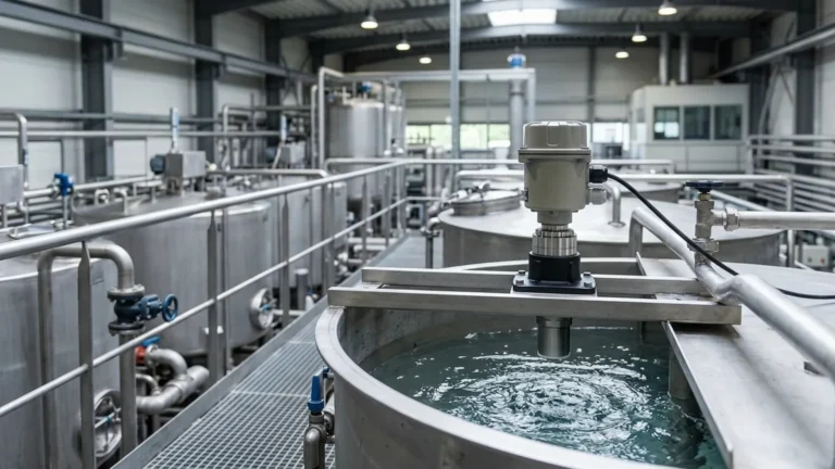
Ge Ultrasonic Meter
Ge Ultrasonic Meter
In the landscape of industrial process control, non-contact measurement has become the gold standard for reliability and hygiene. Among the various technologies available, ultrasonic measurement stands out for its versatility and cost-effectiveness. Many procurement specialists and engineers searching for a "ge ultrasonic meter" are often looking for high-precision solutions capable of handling demanding environments, whether for flow measurement or liquid level monitoring.
This guide explores the engineering principles, selection criteria, and practical application of Ultrasonic Level Meters, providing a technical framework for those evaluating industrial-grade sensing technology.
Understanding the Measurement Principle
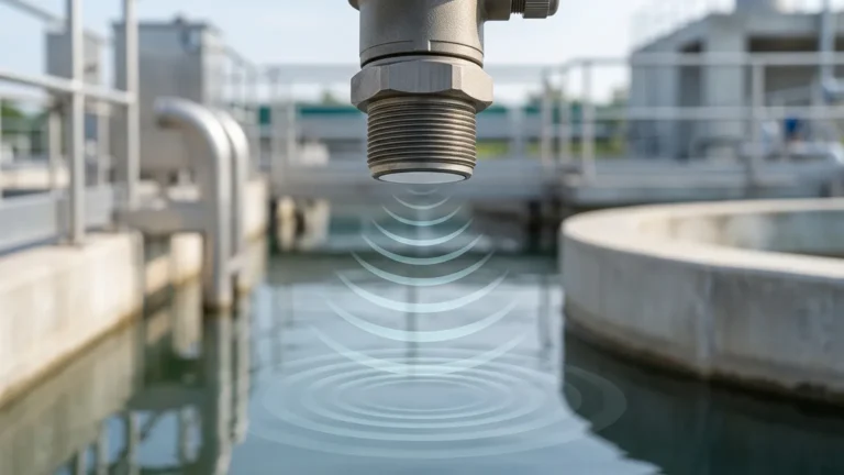
Before selecting a specific instrument, it is essential to understand the physics of ultrasonic waves. Ultrasonic sensors operate on the "Time-of-Flight" (ToF) principle. The device consists of a transducer that acts as both a transmitter and a receiver.
1. Emission: The transducer emits a high-frequency sound pulse (typically between 20 kHz and 200 kHz).
2. Propagation: The sound wave travels through the air (or gas) toward the surface of the material being measured.
3. Reflection: Upon hitting the surface, the sound wave is reflected back toward the sensor as an echo.
4. Reception: The transducer detects the returning echo.
5. Calculation: The internal electronics measure the time interval ($t$) between emission and reception.
The distance ($D$) from the sensor to the surface is calculated using the formula:
$$D = \frac{v \cdot t}{2}$$
Where $v$ is the speed of sound in the medium. By knowing the total height of the vessel ($H$), the device can determine the level ($L$) of the material: $L = H – D$.
The Importance of Temperature Compensation
The speed of sound is not constant; it varies with the temperature of the medium through which it travels. In air, the speed of sound increases by approximately 0.6 meters per second for every degree Celsius increase. A professional-grade ultrasonic meter must include an integrated temperature sensor to provide real-time compensation, ensuring accuracy remains within the specified tolerance (typically ±0.25% to ±0.5% of the measured range).
Evaluating the "GE Ultrasonic Meter" Context
In industrial circles, the term "ge ultrasonic meter" frequently refers to the legacy of high-performance ultrasonic technology developed for complex flow and level applications. These systems are known for their robust signal processing and ability to handle "noisy" environments where weaker sensors might fail.
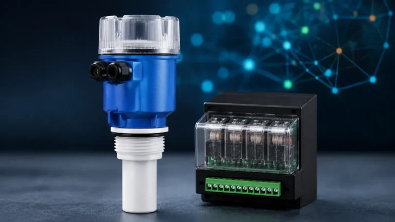
When evaluating such high-end technology against standard industrial Ultrasonic Level Meters, engineers must consider whether the application requires advanced diagnostics, multi-path signal analysis, or specific hazardous area certifications (such as ATEX or IECEx). Modern industrial units, like those manufactured by Welk, often incorporate these advanced digital signal processing (DSP) algorithms to filter out false echoes caused by internal tank obstructions like agitators or ladders.
Practical Selection Criteria
Choosing the right ultrasonic instrument requires a detailed analysis of the process environment. The following table provides a baseline for selecting an appropriate meter based on common industrial parameters.
Selection Table: Industrial Ultrasonic Level Measurement
| Parameter | Standard Application | Demanding Application | High-Precision / GE Style |
| :— | :— | :— | :— |
| Measuring Range | 0.3m to 10m | 0.5m to 30m | Up to 40m+ |
| Media Type | Clean liquids (water) | Slurries, wastewater | Corrosive chemicals |
| Process Temp. | -20°C to +60°C | -40°C to +80°C | Specialized transducers |
| Process Pressure | Atmospheric | Up to 0.3 MPa | Specialized housings |
| Output Signal | 4-20mA, RS485 | HART, Modbus | Foundation Fieldbus, Profibus |
| Accuracy | ±0.5% FS | ±0.25% FS | ±0.1% FS |
| Beam Angle | 10° – 12° | 6° – 9° (Narrow) | < 6° |
Installation Considerations
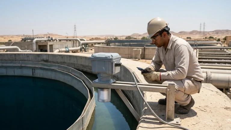
Proper installation is the single most critical factor in the performance of an ultrasonic meter. Even the most advanced ge ultrasonic meter or equivalent industrial sensor will provide inaccurate data if mounted incorrectly.
1. The Blind Zone (Dead Band)
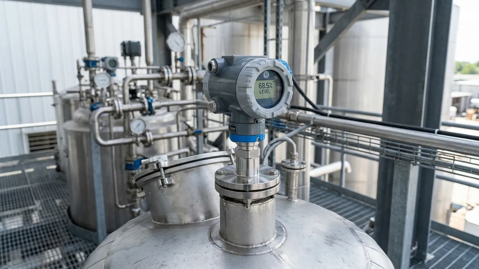
Every ultrasonic sensor has a "blind zone" directly beneath the transducer face where it cannot receive an echo. This is due to the time required for the transducer to stop vibrating after emission before it can switch to receiving mode. Ensure the maximum liquid level never enters this zone (typically 0.2m to 0.5m depending on the frequency).
2. Mounting Angle and Position
The sensor must be mounted perpendicular to the liquid surface. If the sensor is tilted, the sound wave will reflect away from the transducer rather than back to it, resulting in a loss of signal. Additionally, avoid mounting the sensor in the center of a domed tank, as the shape can focus multiple echoes and cause signal interference.
3. Obstructions and the Beam Angle
The ultrasonic pulse spreads out in a cone shape. Any internal obstructions (pipes, reinforcement beams, or agitators) within this cone will generate false echoes.
* Guideline: Maintain a distance from the tank wall of at least 1/6th of the total tank height to avoid wall interference.
* Tip: If obstructions are unavoidable, use a meter with "False Echo Suppression" software to map out and ignore these static reflections.
Limitations of Ultrasonic Technology
While highly effective, Ultrasonic Level Meters are not universal solutions. Engineers should be aware of the following limitations:
* Vacuum Conditions: Sound cannot travel through a vacuum. Ultrasonic meters will not function in vessels under full vacuum.
* Heavy Foam: Dense foam can absorb the ultrasonic pulse rather than reflecting it, leading to signal loss. In these cases, radar or hydrostatic transmitters are preferred.
* High Pressure/High Temperature Steam: Significant steam or vapor can change the composition of the gas through which the sound travels, affecting the speed of sound beyond what standard temperature compensation can fix.
* Dusty Environments: In solid level measurement (like grain or cement), heavy dust during filling can scatter the sound wave.
Maintenance and Troubleshooting
One of the primary advantages of non-contact ultrasonic meters is the lack of moving parts, which significantly reduces maintenance requirements. However, periodic checks are recommended:
1. Transducer Face Cleaning: In humid or dusty environments, condensation or buildup can occur on the transducer face. Wipe it periodically with a soft cloth and mild detergent.
2. Signal Strength Monitoring: Most modern meters provide a "Signal-to-Noise Ratio" (SNR) or echo strength percentage. A gradual decline in this value may indicate a failing transducer or increasing buildup on the sensor.
3. Cable Integrity: Ensure that cable glands are tight and that there is no moisture ingress into the housing, which is a common cause of electronic failure in outdoor installations.
Frequently Asked Questions (FAQ)
Q: Can I use an ultrasonic meter for flow measurement?
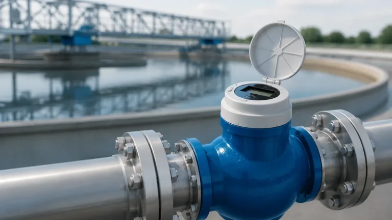
A: Yes. When paired with a flume or weir in an open channel, an ultrasonic level meter can calculate flow rate based on the liquid height using pre-programmed hydraulic formulas. This is a common use for high-accuracy meters.
Q: How does wind affect an outdoor ultrasonic installation?
A: Strong winds can "blow" the ultrasonic pulse away or create turbulence that scatters the echo. For outdoor tanks, using a stilling well or a sensor with a higher power output can mitigate this effect.
Q: What is the difference between a two-wire and a four-wire ultrasonic meter?
A: A two-wire meter is loop-powered (the 4-20mA signal and power share the same wires), which is simpler to install but offers less power for the transducer. A four-wire meter has separate power and signal lines, allowing for more powerful pulses and longer measuring ranges.
Conclusion
Whether you are specifying a "ge ultrasonic meter" for a critical process or integrating standard industrial Ultrasonic Level Meters into a water treatment facility, the success of the project relies on matching the sensor's frequency and signal processing capabilities to the environment. By respecting the physics of sound propagation and following rigorous installation standards, these instruments provide a reliable, low-maintenance solution for modern industrial automation.
For complex applications involving corrosive media or extreme distances, always consult with a technical specialist to confirm that the chosen instrument's beam angle and compensation algorithms are suited for the specific vessel geometry.