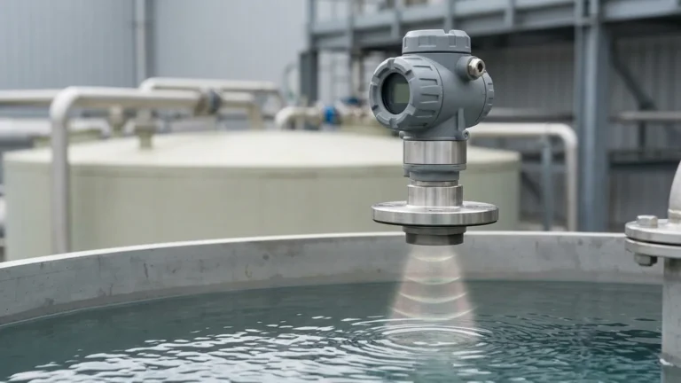
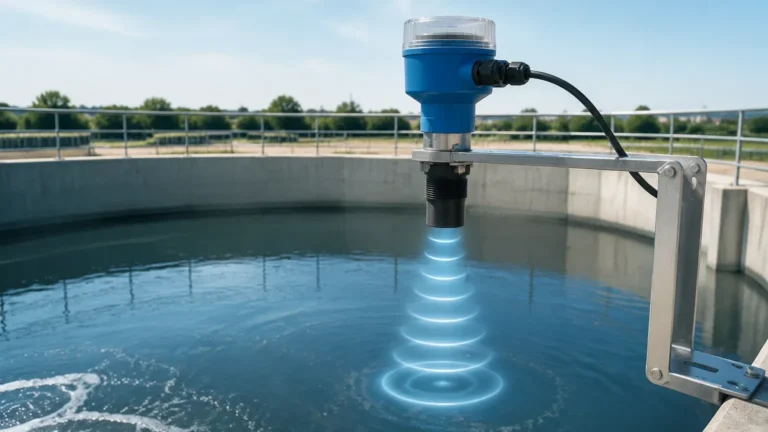
Ultrasonic Level Probe
Ultrasonic Level Probe: A Technical Guide for Industrial Level Measurement
In modern industrial automation, the ability to monitor liquid and solid levels accurately without physical contact is a significant operational advantage. The ultrasonic level probe has emerged as a cornerstone technology for these applications, offering a balance of reliability, ease of maintenance, and cost-effectiveness. As a professional manufacturer, Welk provides advanced Ultrasonic Level Meters designed to meet the rigorous demands of water treatment, chemical processing, and oil and gas industries.
This guide provides a comprehensive technical overview of ultrasonic level measurement, covering its fundamental principles, selection criteria, installation best practices, and the limitations that engineers must consider when specifying these instruments.
Understanding the Measurement Principle
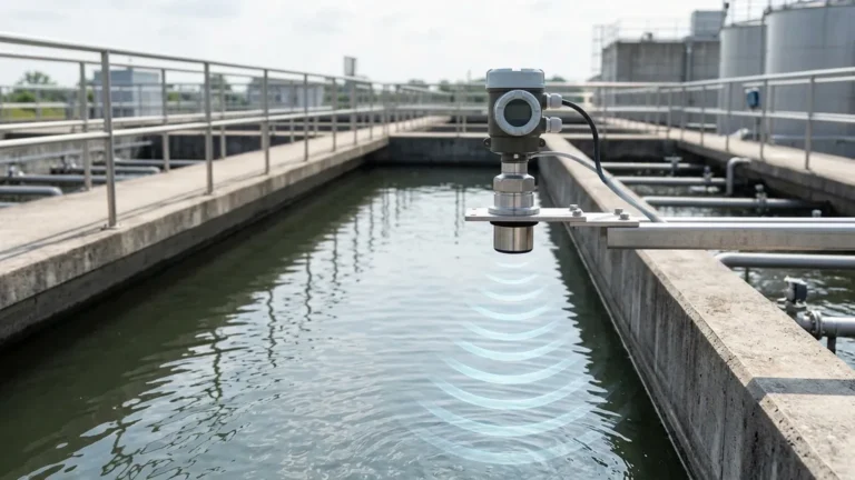
Ultrasonic level measurement is based on the "Time-of-Flight" (ToF) principle. This method relies on the propagation of sound waves through a medium—typically air—to determine the distance between the sensor and the surface of the material being measured.
The Piezoelectric Effect
At the heart of every ultrasonic level probe is a transducer containing one or more piezoelectric crystals. When an electrical pulse is applied to these crystals, they vibrate at a high frequency, generating an ultrasonic sound wave. This wave travels through the air at a known velocity (the speed of sound).
The Echo Sequence
1. Emission: The probe emits a short burst of ultrasonic energy.
2. Propagation: The sound wave travels downward toward the target material.
3. Reflection: Upon hitting the surface of the liquid or solid, a portion of the sound energy is reflected back toward the probe as an echo.
4. Detection: The transducer receives the returning echo and converts the mechanical vibration back into an electrical signal.
The Calculation
The internal processor of the meter calculates the distance ($D$) using the formula:
$$D = \frac{c \times t}{2}$$
Where:
* $c$ is the speed of sound in the medium (approximately 344 m/s in air at 20°C).
* $t$ is the total time elapsed between emission and reception.
The level ($L$) is then determined by subtracting the measured distance ($D$) from the total height of the tank or vessel ($H$): $L = H – D$.
Temperature Compensation
The speed of sound is not constant; it varies significantly with air temperature. For instance, sound travels faster in warmer air. To maintain accuracy, a high-quality ultrasonic level probe includes an integrated temperature sensor. The device automatically adjusts the calculation based on the ambient temperature near the transducer to ensure precision across varying environmental conditions.
Key Components and Configurations
When evaluating Ultrasonic Level Meters, it is essential to understand the two primary hardware configurations available in the market:
1. Integrated (Compact) Type: The transducer (the probe) and the electronics/display are housed in a single unit. This is ideal for standard tank applications where space is limited and local monitoring is required at the mounting point.
2. Split (Remote) Type: The ultrasonic level probe is mounted at the measurement point, while the transmitter/controller is installed in a remote location (such as a control room or a lower-level wall). This configuration is preferred for hazardous environments or where the probe is difficult to access for maintenance.
Selection Criteria for Industrial Applications
Selecting the right probe requires a detailed analysis of the process environment. Using an incorrectly specified probe can lead to signal loss or inaccurate readings.
Measuring Range
Probes are rated for specific maximum ranges, typically from 5 meters (16.4 ft) to 30 meters (98.4 ft). It is generally recommended to select a probe with a range 20% greater than the actual depth of the vessel to account for potential signal attenuation.
Material Compatibility
The housing material of the probe must be compatible with the vapors present in the tank. While ABS or PVC is standard for water, corrosive chemical environments (such as those involving sulfuric acid or caustic soda) require probes made from PVDF (Polyvinylidene Fluoride) or PTFE (Teflon).
Output and Communication
Standard industrial probes offer a 4-20mA analog output. However, for integration into modern SCADA or PLC systems, digital protocols like RS485 (Modbus), HART, or Profibus are often required.
Practical Selection Table
| Feature | Standard Water Probe | Chemical-Resistant Probe | Long-Range Solids Probe |
| :— | :— | :— | :— |
| Max Range | 10m (32.8 ft) | 15m (49.2 ft) | 30m (98.4 ft) |
| Probe Material | ABS / Nylon | PVDF | Reinforced Polymer |
| Beam Angle | 8° – 10° | 6° – 9° | 5° |
| Protection Rate | IP65 / IP67 | IP68 | IP66 / IP67 |
| Typical Use | Wastewater, Reservoirs | Acid Tanks, Chemical Storage | Grain Silos, Ore Hoppers |
Installation Considerations
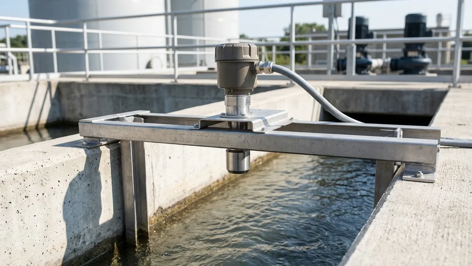
Proper installation is the most critical factor in the performance of an ultrasonic level probe. Even the most advanced sensor will fail if it is poorly positioned.
1. The Dead Zone (Blocking Distance)
Every ultrasonic probe has a "Dead Zone" immediately below the transducer face, typically ranging from 0.25m to 0.6m (10 to 24 inches). In this zone, the transducer cannot switch from "transmit" to "receive" mode fast enough to capture the echo. The probe must be mounted high enough so that the maximum liquid level never enters this dead zone.
2. Beam Angle and Obstructions
The ultrasonic pulse spreads out in a cone shape. Any internal structures within this cone—such as ladders, pipes, agitators, or even weld seams—will create false echoes.
* Rule of Thumb: The probe should be installed at a distance from the tank wall equal to at least 1/6th of the tank height.
* Clearance: Ensure the path is clear of any physical obstructions that could intercept the signal.
3. Orientation
The probe must be mounted perfectly perpendicular to the surface of the medium. If the probe is tilted, the sound wave will reflect off the surface at an angle and may not return to the transducer, resulting in a "Loss of Echo" (LOE) error.
4. Mounting Location
* Avoid the Inflow: Do not mount the probe directly above the point where liquid enters the tank. The turbulence and air entrainment caused by the inflow will disrupt the signal.
* Stilling Wells: In tanks with heavy agitation or surface foam, installing the probe inside a stilling well (a vertical pipe) can provide a calm surface for accurate measurement.
Limitations and Environmental Challenges
While highly versatile, ultrasonic technology is not a universal solution. Engineers should be aware of the following physical limitations:
* Vacuum Conditions: Sound waves require a medium (air or gas) to travel. Therefore, ultrasonic probes cannot function in a vacuum.
* High Pressure: Significant changes in pressure alter the density of the air, which affects the speed of sound. Most standard probes are limited to pressures below 3 bar (43.5 psi).
* Heavy Foam: Dense foam acts as an acoustic insulator, absorbing the ultrasonic pulse rather than reflecting it. In cases of heavy foaming, radar level meters are often a better alternative.
* Dust and Vapor: While light dust is manageable, extremely heavy dust (in silos) or thick steam/vapor can attenuate the signal. High-power transducers with self-cleaning faces are often used to mitigate these effects.
Maintenance and Troubleshooting
One of the primary benefits of an ultrasonic level probe is its low maintenance requirement due to the lack of moving parts. However, periodic checks are recommended:
1. Transducer Face Cleaning: In humid or dusty environments, condensation or buildup can occur on the sensor face. Gently wipe the face with a soft cloth and water (avoid solvents).
2. Signal Strength Monitoring: Most modern meters provide a diagnostic value for signal quality. A declining signal strength often indicates either buildup on the probe or a change in the process (e.g., increased foaming).
3. Check Cable Integrity: Ensure that the shielding on the signal cable is intact to prevent electromagnetic interference (EMI) from nearby high-voltage equipment.
Frequently Asked Questions (FAQs)
Q: Can ultrasonic probes measure solids like grain or sand?
A: Yes, but with caveats. Solids do not reflect sound as efficiently as liquids and often have an "angle of repose" that deflects the signal. A probe with a higher power output and a narrower beam angle is usually required for solids.
Q: How does wind affect an outdoor ultrasonic installation?
A: Strong crosswinds can "blow" the ultrasonic pulse away from its vertical path, leading to inconsistent readings. For outdoor reservoirs, using a protective shroud or a stilling well is recommended.
Q: What is the difference between an ultrasonic level probe and a radar level meter?
A: Ultrasonic probes use sound waves and are generally more cost-effective for standard applications. Radar meters use electromagnetic waves, which are unaffected by vacuum, high temperature, or pressure, making them suitable for more extreme process conditions.
Conclusion
The ultrasonic level probe remains one of the most reliable and efficient tools for industrial level monitoring. By understanding the physics of sound propagation and adhering to strict installation guidelines, plant operators can achieve high-precision measurements with minimal upkeep. Whether managing wastewater treatment or monitoring chemical inventory, selecting the appropriate Ultrasonic Level Meters is a critical step toward optimizing process efficiency and safety.
For complex applications involving high temperatures or heavy foam, consulting with a technical specialist is advised to ensure the selected instrumentation aligns with the specific physical constraints of the environment.