Ultrasonic Level Sensor Explosion Proof
Ultrasonic Level Sensor Explosion Proof: Engineering Selection and Application Guide
In industrial environments where flammable gases, vapors, or combustible dusts are present, instrumentation safety is not merely a preference but a regulatory necessity. For liquid and solid level monitoring, Ultrasonic Level Meters have become a standard due to their non-contact nature. However, when these instruments are deployed in hazardous zones—such as oil refineries, chemical processing plants, or wastewater treatment facilities—the hardware must meet stringent "explosion-proof" or "intrinsically safe" standards.
An ultrasonic level sensor explosion proof design ensures that the electronic components within the device cannot ignite the surrounding atmosphere, either by containing an internal explosion or by limiting the electrical energy to levels incapable of causing ignition. This guide provides a technical deep dive into the principles, selection criteria, and installation requirements for these specialized instruments.
Measurement Principles of Ultrasonic Technology
Before evaluating safety ratings, it is essential to understand how ultrasonic technology functions. Ultrasonic level measurement is based on the "Time-of-Flight" (ToF) principle.
The Transducer and Pulse Emission
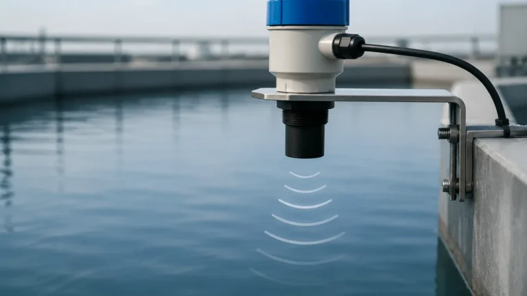
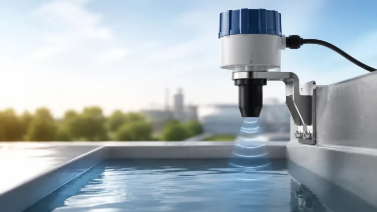
The core of the sensor is a piezoelectric crystal located within the transducer. When excited by an electrical signal, this crystal vibrates at a specific frequency (typically between 20 kHz and 200 kHz), emitting a burst of sound waves. These waves travel through the air (or gas space) toward the surface of the medium being measured.
Reflection and Echo Processing
Upon hitting the surface of the liquid or solid, the sound waves are reflected back toward the sensor. The transducer then acts as a receiver, converting the mechanical energy of the returning echo back into an electrical signal. The internal microprocessor calculates the time elapsed between emission and reception ($t$).
Distance Calculation
The distance ($D$) from the sensor to the material surface is calculated using the formula:
$$D = \frac{v \times t}{2}$$
Where:
* $v$ is the speed of sound in the medium (typically air, approximately 340 m/s at 20°C).
* $t$ is the total travel time.
Since the speed of sound is sensitive to temperature fluctuations, high-quality Ultrasonic Level Meters include integrated temperature sensors to compensate for these changes automatically, ensuring accuracy remains within 0.25% to 0.5% of the measured range.
Defining "Explosion Proof" in Level Sensing
When we discuss an ultrasonic level sensor explosion proof model, we are referring to specific protection methods designed to prevent the ignition of hazardous atmospheres. There are two primary approaches used in the design of these sensors:
1. Flameproof/Explosion-Proof (Ex d): The sensor electronics are housed in a heavy-duty enclosure (often cast aluminum or stainless steel) designed to withstand an internal explosion without allowing flames or hot gases to escape and ignite the external environment.
2. Intrinsically Safe (Ex i): The circuit design limits the electrical and thermal energy to a level below what is required to ignite a specific hazardous atmospheric mixture, even under fault conditions.
For most ultrasonic applications, the "Explosion-Proof" designation implies a ruggedized housing and sealed cable entries, making the device suitable for Zone 1 or Zone 2 (or Class I, Div 1/2) environments.
Technical Selection Criteria
Choosing the right sensor requires balancing the physical properties of the medium with the safety requirements of the site. The following table outlines typical specifications for standard vs. explosion-proof ultrasonic sensors.
Selection Table: Industrial Ultrasonic Level Sensors
| Feature | Standard Industrial Model | Explosion-Proof (Ex d / Ex i) |
| :— | :— | :— |
| Measuring Range | 0.3m to 30m | 0.3m to 20m (Typical) |
| Housing Material | ABS / Nylon / Polycarbonate | Die-cast Aluminum / 316L SS |
| Transducer Material | PVC / PVDF | PVDF / PTFE / ETFE |
| Output Signal | 4-20mA, RS485 | 4-20mA (HART), Modbus |
| Power Supply | 24V DC / 220V AC | 24V DC (Loop Powered) |
| Protection Grade | IP65 / IP66 | IP67 / IP68 |
| Hazardous Rating | None | ATEX/IECEx Zone 0, 1, or 2 |
| Accuracy | 0.5% FS | 0.25% – 0.5% FS |
Key Evaluation Factors
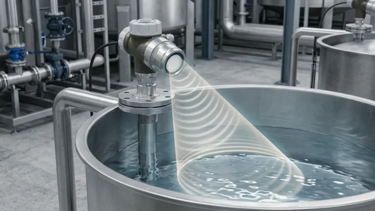
* Beam Angle: A narrower beam angle (typically 5° to 12°) is preferred to avoid interference from tank walls, internal ladders, or agitators.
* Dead Zone (Blocking Distance): This is the area directly beneath the transducer where measurements are impossible. For a 10-meter range sensor, the dead zone is usually between 0.25m and 0.5m. The sensor must be mounted high enough so the liquid never enters this zone.
* Chemical Compatibility: In hazardous chemical storage, the transducer face must be resistant to corrosive vapors. PVDF (Polyvinylidene fluoride) is the standard choice for aggressive acids and bases.
Installation Considerations in Hazardous Areas
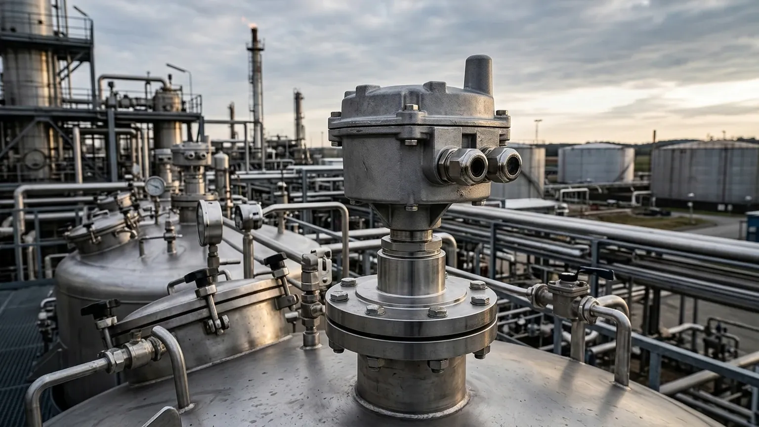
Proper installation of an ultrasonic level sensor explosion proof unit is critical to maintaining its safety certification. Failure to follow specific wiring and mounting protocols can void the protection rating.
1. Mounting Position and Orientation
* Perpendicularity: The transducer face must be perfectly horizontal (parallel to the liquid surface). A tilt of even a few degrees can result in the signal reflecting away from the sensor, causing "lost echo" errors.
* Wall Distance: To prevent false echoes from the tank wall, the sensor should be installed at a distance from the wall equal to at least 1/6th of the tank height.
* Avoid Obstructions: Ensure the "signal cone" is clear of pipes, brackets, or inflow streams. If obstructions are unavoidable, many modern meters offer "False Echo Suppression" software to mask these static reflections.
2. Electrical and Wiring Safety
* Cable Glands: Only certified explosion-proof cable glands (Ex d or Ex e) must be used. These glands provide a gas-tight seal around the power/signal cable.
* Conduit Sealing: If using conduit, a sealing fitting (pour seal) must be installed within 45 cm (18 inches) of the device to prevent the passage of explosive gases through the conduit system.
* Grounding: Proper equipotential bonding is mandatory. The metal housing of the sensor must be connected to the plant’s grounding system to prevent static buildup.
3. Environmental Shielding
While explosion-proof sensors are rugged, they are still sensitive to extreme direct sunlight, which can heat the housing and affect the internal temperature compensation. A simple sunshade is recommended for outdoor installations in tropical or desert climates.
Limitations and Challenges
Despite their versatility, ultrasonic level meters face physical limitations that engineers must account for during the design phase.
* Vacuum Conditions: Ultrasonic waves require a medium (gas/air) to travel. They cannot function in a vacuum.
* High Pressure: As pressure increases, the density of the gas changes, which can attenuate the ultrasonic signal. Generally, ultrasonic sensors are limited to applications under 0.3 MPa (3 bar).
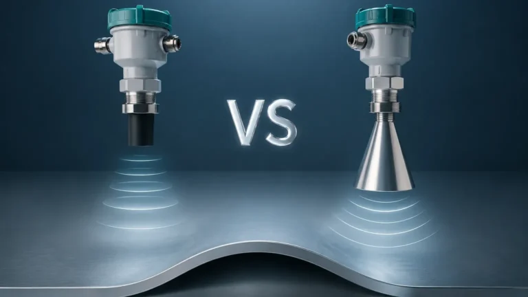
* Heavy Foam: Thick, dense foam on the surface of a liquid absorbs the ultrasonic pulse rather than reflecting it. In such cases, radar level meters or magnetic level gauges are often better alternatives.
* Dust and Vapor: While light dust is manageable, extremely heavy dust (e.g., in a cement silo) or dense steam can scatter the sound waves, reducing the effective range of the sensor.
Maintenance and Troubleshooting
Maintenance for an ultrasonic level sensor explosion proof is generally minimal due to the lack of moving parts. However, periodic checks are advised:
1. Transducer Cleaning: In applications with condensing vapors or splashing, a buildup of residue may occur on the transducer face. This should be cleaned with a soft cloth and mild solvent (ensure the solvent is compatible with the transducer material, such as PVDF).
2. Seal Integrity: Inspect the O-rings and cover gaskets during routine safety audits to ensure no moisture or corrosive gas has entered the electronics compartment.
3. Signal Strength Monitoring: Most digital ultrasonic meters provide a "Signal-to-Noise Ratio" (SNR) or echo strength value. A gradual decline in this value may indicate a dirty transducer or a changing process condition (like increased turbulence).
Frequently Asked Questions (FAQ)
Q: Can I use a standard ultrasonic sensor in a Zone 2 area if I put it in a secondary enclosure?
A: No. The sensor itself must be certified for the specific zone. Using a non-certified device in a hazardous area, even within another box, violates safety codes and creates significant liability and risk.
Q: What is the difference between ATEX and IECEx?
A: ATEX is a mandatory European certification for equipment used in explosive atmospheres. IECEx is an international certification scheme. Many explosion-proof sensors carry both certifications to ensure global compliance.
Q: Does the explosion-proof rating affect the measurement accuracy?
A: No. The rating refers to the mechanical and electrical safety of the housing and circuitry. The measurement accuracy is determined by the transducer frequency and the quality of the signal processing algorithms.
Q: How do I handle level measurement if the liquid is boiling?
A: Boiling liquids create surface turbulence and steam, both of which interfere with ultrasonic waves. For boiling liquids, a guided wave radar or a hydrostatic pressure transmitter is usually recommended over an ultrasonic sensor.
Conclusion
The deployment of an ultrasonic level sensor explosion proof is a critical step in ensuring both process efficiency and site safety. By understanding the Time-of-Flight principle and adhering to strict hazardous area installation standards, engineers can achieve reliable, non-contact level monitoring in the most demanding environments. When selecting a device, always prioritize certified housing materials, appropriate chemical resistance for the transducer, and a clear understanding of the environmental limitations of ultrasonic technology. For complex applications, consulting with a specialized manufacturer like Welk ensures that the selected instrument meets both the technical and regulatory requirements of the project.