Ultrasonic Level Sensor Module
Ultrasonic Level Sensor Module: A Technical Guide for Industrial Integration
In the landscape of industrial automation, non-contact level measurement has become a standard for reliability and hygiene. At the heart of this technology lies the ultrasonic level sensor module, a sophisticated component that converts acoustic energy into actionable data. For engineers and system integrators, understanding the nuances of these modules is essential for ensuring accuracy in applications ranging from municipal water treatment to complex chemical processing.
As a professional manufacturer, Welk provides high-performance Ultrasonic Level Meters designed to withstand the rigors of industrial environments. This guide explores the fundamental principles, selection criteria, and practical installation strategies for integrating ultrasonic level sensor modules into industrial frameworks.
Understanding the Measurement Principle
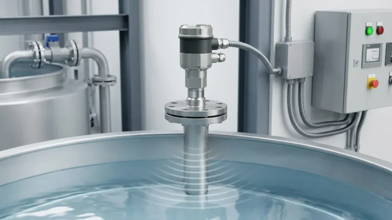
The operation of an ultrasonic level sensor module is based on the "Time-of-Flight" (ToF) principle. This method relies on the propagation of high-frequency sound waves—typically above the range of human hearing (20 kHz to 200 kHz)—to determine the distance between the sensor and the surface of a material.
The Transduction Process
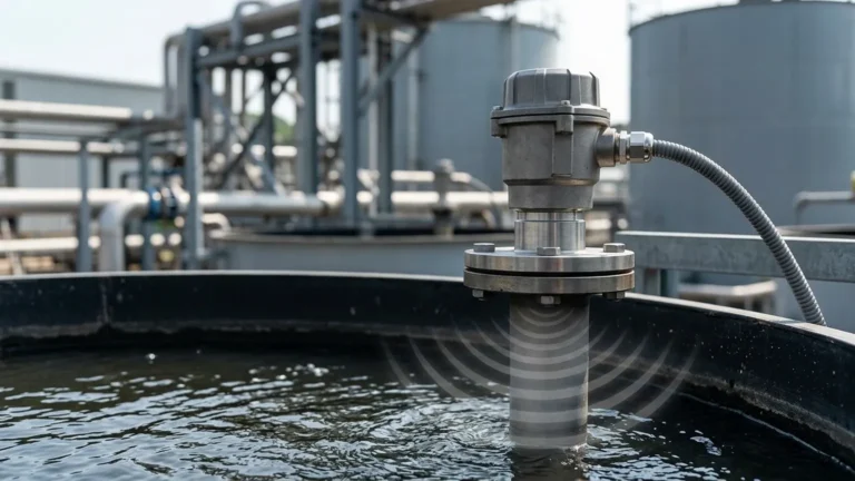
The process begins with a piezoelectric crystal located within the module. When an electrical pulse is applied, the crystal vibrates, generating a burst of ultrasonic waves. these waves travel through the air medium until they encounter a change in acoustic impedance, such as the surface of a liquid or solid. A portion of the energy is reflected back toward the sensor as an echo.
Distance Calculation
The module’s internal microprocessor measures the precise time interval between the transmission of the pulse and the reception of the echo. The distance is calculated using the following formula:
D = (c × t) / 2
Where:
* D is the distance to the surface (meters).
* c is the speed of sound in the medium (approximately 340 m/s in air at 15°C).
* t is the total travel time (seconds).
Because the speed of sound is heavily influenced by air temperature (increasing by approximately 0.6 m/s per degree Celsius), industrial-grade modules incorporate integrated temperature sensors to provide real-time compensation, ensuring measurement stability across fluctuating seasonal or process temperatures.
The Role of the Ultrasonic Level Sensor Module
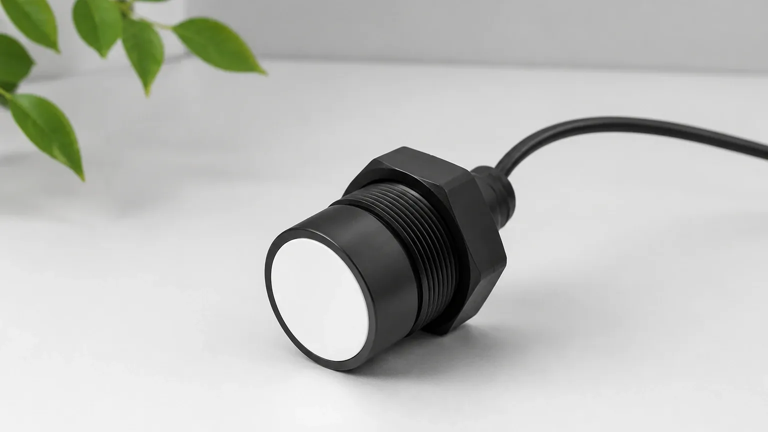
While a complete level meter includes a housing, display, and user interface, the ultrasonic level sensor module is the core functional unit. In B2B contexts, these modules are often sought for OEM (Original Equipment Manufacturer) integration into specialized machinery, remote monitoring stations, or IoT-enabled environmental sensors.
These modules typically consist of:
1. The Transducer: The "face" of the sensor that emits and receives sound.
2. Signal Processing Circuitry: Filters noise and amplifies weak echoes.
3. Communication Interface: Provides data output via protocols such as RS485 (Modbus), 4-20mA analog signals, or UART for direct microcontroller communication.
Key Evaluation Criteria for Industrial Applications
Selecting the correct module requires a deep dive into the technical specifications to ensure compatibility with the intended environment.
1. Measuring Range and Frequency
The frequency of the ultrasonic pulse determines the range and sensitivity. Lower frequencies (e.g., 40 kHz) travel further and are better suited for long-range measurements (up to 30 meters) but have lower resolution. Higher frequencies (e.g., 200 kHz) offer superior precision for short-range applications (under 3 meters) but dissipate more quickly.
2. The Blanking Distance (Blind Zone)
Every ultrasonic module has a "blind zone" directly in front of the transducer face. During the time the transducer is vibrating to send a pulse, it cannot simultaneously listen for an echo. If the material surface is within this zone (typically 0.2m to 0.5m), the sensor will fail to provide an accurate reading. Engineers must account for this when designing tank mounts.
3. Beam Angle
The beam angle defines the spread of the ultrasonic pulse. A narrow beam angle (e.g., 5° to 10°) is preferable in narrow tanks or vessels with internal obstructions like ladders or agitators, as it reduces the risk of false echoes from the tank walls.
4. Ingress Protection (IP Rating)
For industrial use, modules must be sealed against moisture and dust. An IP67 or IP68 rating is standard for modules used in water treatment or outdoor silos to prevent failure due to condensation or submersion.
Comparative Selection Table
The following table provides a general reference for choosing an ultrasonic level sensor module based on typical industrial requirements.
| Feature | Short-Range Module | Standard Industrial Module | Long-Range Module |
| :— | :— | :— | :— |
| Measuring Range | 0.1m – 3.0m | 0.4m – 10.0m | 0.8m – 30.0m |
| Frequency | 150 – 200 kHz | 60 – 80 kHz | 30 – 40 kHz |
| Resolution | 1 mm | 2 – 5 mm | 10 mm |
| Beam Angle | 5° – 8° | 10° – 12° | 12° – 15° |
| Typical Use | Small chemical tanks, lab equipment | Water sumps, fuel tanks | Large silos, open channel flow |
Installation Best Practices and Considerations
Even the most advanced ultrasonic level sensor module will perform poorly if installed incorrectly. Follow these engineering guidelines to ensure optimal signal integrity.
Positioning and Alignment
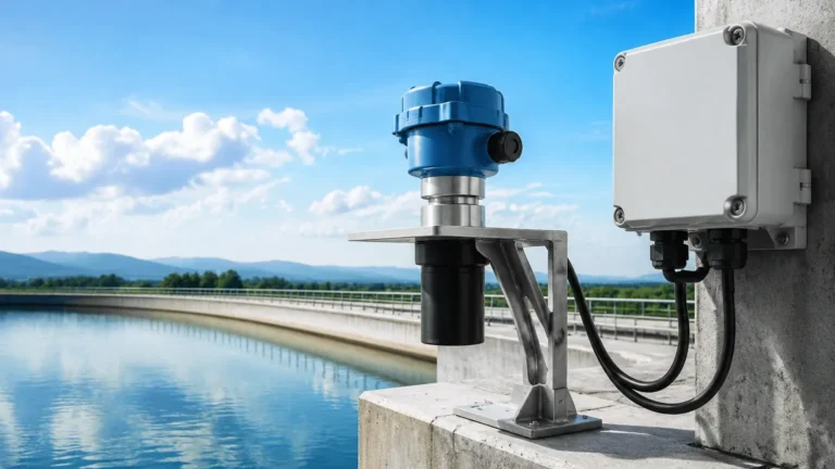
The sensor must be mounted perpendicular to the liquid surface. If the sensor is tilted, the ultrasonic pulse will reflect away from the transducer rather than back to it, resulting in a "Loss of Echo" error. In applications with solids (like grain), the angle of repose must be considered, often requiring adjustable mounting flanges.
Avoiding Obstructions
The "clearance zone" should be free of any physical objects. If a ladder or pipe enters the path of the beam, the module may lock onto that object instead of the liquid level. Modern modules from Welk utilize advanced false-echo suppression software to "map out" these static obstructions, but physical clearance remains the best practice.
Environmental Factors
* Vapor and Steam: Heavy steam or chemical vapors can change the density of the air, affecting the speed of sound and potentially absorbing the signal. In such cases, high-power modules or radar-based alternatives may be required.
* Foam: Surface foam acts as an acoustic absorber. Light, airy foam can completely dissipate the ultrasonic pulse, leading to inaccurate readings. If foam is a constant factor, a stilling well can be used to provide a clear liquid surface for the sensor.
* Turbulence: Rapidly moving or agitated liquids can scatter the echo. Signal averaging and damping settings within the module software can help stabilize the output.
Limitations and Common Risks
While versatile, ultrasonic level sensor modules are not universal solutions. Understanding their limitations prevents costly project delays.
1. Vacuum Applications: Sound waves require a medium (air or gas) to travel. Therefore, ultrasonic sensors cannot function in a vacuum.
2. High-Pressure Environments: Significant changes in pressure alter the acoustic impedance of the air, which can lead to measurement errors if the module is not specifically calibrated for those conditions.
3. Temperature Gradients: If there is a large temperature difference between the sensor face and the liquid surface (e.g., in a heated tank), the speed of sound will vary along the path, leading to inaccuracies despite internal compensation.
Frequently Asked Questions (FAQ)
Q: Can an ultrasonic level sensor module measure the level of solids?
A: Yes, but with caveats. Solids like powders, grains, or ores absorb more sound than liquids and often have an uneven surface. A module with a higher power output and a lower frequency is typically required for reliable solids measurement.
Q: How do I handle the blind zone if my tank needs to be filled to the top?
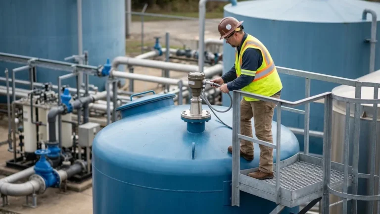
A: The most common solution is to install the sensor on a nozzle or a stand-off pipe. This raises the sensor higher above the tank, ensuring that even when the tank is full, the liquid level remains outside the blanking distance.
Q: Is it possible to use these modules in explosive environments?
A: Only if the module is housed in an appropriately certified enclosure (e.g., ATEX or IECEx certified). Welk offers specialized versions of Ultrasonic Level Meters specifically designed for hazardous areas in the oil and gas or chemical industries.
Q: What is the typical lifespan of an ultrasonic transducer?
A: In standard conditions, an industrial transducer can last 7 to 10 years. However, exposure to highly corrosive chemical vapors can degrade the transducer face over time if a chemical-resistant material (like PVDF) is not selected.
Conclusion
The ultrasonic level sensor module is a cornerstone of modern industrial level measurement, offering a balance of accuracy, ease of maintenance, and cost-effectiveness. By carefully considering the measuring range, environmental constraints, and proper installation techniques, engineers can implement robust systems that provide reliable data for years to come. For those seeking integrated solutions or customized OEM modules, Welk continues to lead the industry with advanced technology and comprehensive application support.