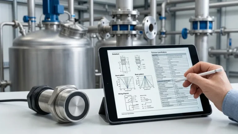
Ultrasonic Level Meter Nus 7
Understanding the Ultrasonic Level Meter NUS 7: A Technical Guide to Non-Contact Measurement
In the landscape of industrial automation, selecting the correct instrumentation for fluid and solid level monitoring is critical for operational efficiency and safety. Among the various technologies available, Ultrasonic Level Meters remain a primary choice for engineers due to their non-contact nature, ease of installation, and cost-effectiveness. The ultrasonic level meter NUS 7 represents a specific class of compact, loop-powered ultrasonic transmitters designed to provide reliable data in diverse process environments.
This guide explores the technical principles, selection criteria, and installation best practices for ultrasonic level measurement, with a focus on the capabilities typically found in high-performance units like the NUS 7 series.
Measurement Principles: How Ultrasonic Sensors Work
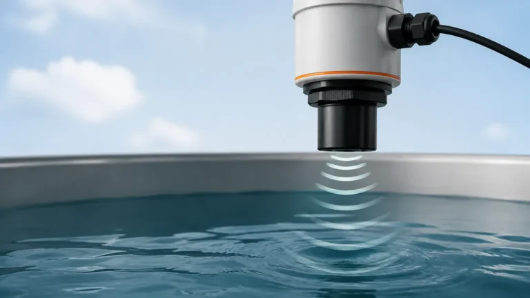
Ultrasonic level measurement is based on the "Time of Flight" (ToF) principle. The instrument’s transducer emits a high-frequency ultrasonic pulse toward the surface of the medium being measured. This pulse travels through the air, reflects off the surface of the liquid or solid, and returns to the transducer.
The Calculation
The distance from the sensor to the material surface is calculated using the following formula:
D = (c × t) / 2
* D: Distance to the surface.
* c: The speed of sound in the medium (usually air).
* t: The time elapsed between the emission and the reception of the pulse.
Since the height of the vessel (H) is known, the level (L) of the material is determined by subtracting the measured distance (D) from the total height: L = H – D.
Temperature Compensation
The speed of sound is not constant; it varies with the temperature of the air through which it travels. For instance, at 0°C, the speed of sound is approximately 331.5 m/s, while at 20°C, it increases to roughly 343 m/s. To maintain accuracy, modern instruments like the ultrasonic level meter NUS 7 include an integrated temperature sensor to automatically compensate for these fluctuations in real-time.
Key Features of the Ultrasonic Level Meter NUS 7
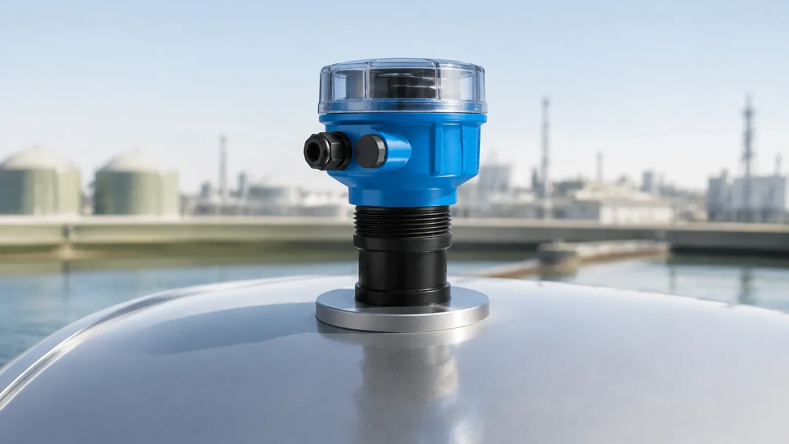
The NUS 7 series is characterized by its compact design, integrating the sensor and the electronics into a single housing. This design is particularly advantageous for space-constrained applications and simplified wiring.
* Non-Contact Measurement: Since the sensor never touches the medium, it is ideal for corrosive, viscous, or coating liquids that would otherwise damage contact-based sensors like float switches or pressure transmitters.
* 2-Wire Technology: Most units in this category utilize a 4-20 mA loop-powered system, reducing cabling costs and simplifying integration into existing PLC or SCADA systems.
* Programming Flexibility: These meters often feature digital displays and push-button programming, allowing users to set the measuring range, damping, and fail-safe modes directly at the device.
* Material Compatibility: Probes are typically constructed from chemically resistant materials such as Polypropylene (PP) or PVDF, ensuring longevity in harsh chemical environments.
Practical Selection Criteria
When evaluating an ultrasonic level meter NUS 7 for your project, several technical parameters must be harmonized with the application requirements.
1. Measuring Range and Blocking Distance
Every ultrasonic sensor has a "blocking distance" (also known as the dead zone or blanking zone). This is the area immediately below the transducer face where the sensor cannot accurately process a return signal because the pulse is still being transmitted. For an NUS 7 type meter, this zone is typically between 0.2 meters and 0.5 meters. If the liquid level enters this zone, the reading will become erratic or fixed at the maximum value.
2. Beam Angle
The ultrasonic pulse spreads out in a cone shape. The beam angle (usually between 5° and 10°) determines the footprint of the signal at the maximum range. Engineers must ensure that no internal tank obstructions—such as ladders, agitators, or heating coils—interfere with this beam, as they will cause false echoes.
3. Process Conditions
* Pressure: Standard ultrasonic meters are designed for atmospheric or near-atmospheric pressure. High pressure changes the density of the air, significantly affecting the speed of sound and measurement accuracy.
* Vapors and Dust: Heavy steam or thick dust can attenuate the ultrasonic signal, leading to signal loss. In such cases, high-power transducers or radar level meters may be required.
Selection Table: Ultrasonic Level Meter Specifications
| Feature | Compact Ultrasonic (NUS 7 Style) | High-Power Ultrasonic |
| :— | :— | :— |
| Typical Range | 0.25m to 8m | Up to 30m |
| Output | 4-20 mA / HART | 4-20 mA / Modbus / Relays |
| Housing Material | Plastic (PP/PVDF) | Aluminum or Stainless Steel |
| Accuracy | ±0.2% of full scale | ±0.1% of full scale |
| Power Supply | 12-30 VDC (Loop powered) | 24 VDC or 110/230 VAC |
| Best Use Case | Small tanks, sumps, IBCs | Large silos, deep wells |
Installation Considerations
Proper mechanical installation is the most critical factor in ensuring the long-term reliability of an ultrasonic level meter.
1. Perpendicular Alignment: The transducer face must be perfectly parallel to the liquid surface. A tilt of even a few degrees can cause the reflected signal to bounce away from the receiver, resulting in a "Lost Echo" error.
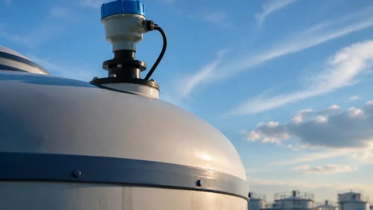
2. Avoid the Center: In tanks with domed tops, do not mount the sensor in the exact center. The parabolic shape of the roof can focus multiple reflections back to the sensor, creating interference.
3. Filling Stream: Never install the sensor directly above the inlet pipe or the path of the falling product. The turbulence and the product stream will block the ultrasonic pulse.
4. Standpipes: If the tank surface is turbulent or covered in foam, installing the sensor inside a standpipe (still-well) can help provide a stable surface for measurement. The pipe must have a vent hole at the top to equalize pressure.
Limitations and Challenges
While the ultrasonic level meter NUS 7 is a versatile tool, it is not a universal solution. Understanding its limitations prevents costly specification errors.
* Foam: Heavy, dense foam acts as an acoustic insulator, absorbing the ultrasonic pulse rather than reflecting it. If foam is present, a hydrostatic pressure transmitter or a guided wave radar is usually a better choice.
* Vacuum: Sound waves require a medium (air or gas) to travel. Therefore, ultrasonic meters cannot function in a vacuum.
* Extreme Temperatures: Most compact ultrasonic meters are rated for process temperatures between -30°C and +80°C. Beyond this, the transducer materials may degrade, and the air density changes too drastically for reliable compensation.
Frequently Asked Questions (FAQs)
Q: Can the ultrasonic level meter NUS 7 be used for solids?
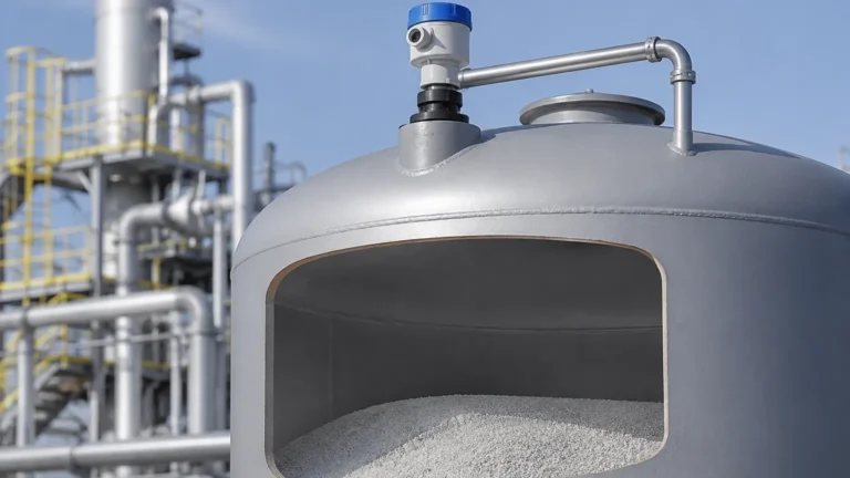
A: Yes, but with caveats. Solids like grain or plastic pellets have an angle of repose, which reflects the signal away from the sensor. The effective range for solids is typically half the rated range for liquids, and the sensor should be mounted with an adjustable flange to aim at the material surface.
Q: How do I handle condensation on the sensor face?
A: Condensation can attenuate the signal. Many NUS 7 models feature a convex transducer face to encourage droplets to run off. In high-humidity applications, choosing a model with a higher acoustic power output can help "punch through" the moisture.
Q: What is the difference between 2-wire and 4-wire ultrasonic meters?
A: A 2-wire meter (like many NUS 7 versions) uses the same two wires for both power supply and the 4-20 mA output signal. A 4-wire meter has separate pairs for power and signal, allowing for higher power consumption, which is often needed for longer ranges or driving internal relays.
Conclusion for Process Engineers
The ultrasonic level meter NUS 7 offers a balance of simplicity and performance for standard industrial level monitoring. By understanding the acoustic properties of the application and following strict installation guidelines regarding beam angles and blocking distances, engineers can achieve high-precision measurements with minimal maintenance requirements.
For applications involving aggressive chemicals, water treatment sumps, or intermediate bulk containers (IBCs), this technology provides a robust alternative to mechanical level indicators. When selecting your device, always verify the chemical compatibility of the wetted parts and ensure the measuring range accounts for the necessary safety margins above the maximum liquid level.
For further technical specifications and to compare different transducer options, you can Review product options and application support to find the ideal configuration for your specific industrial environment.