Ultrasonic Level Sensor Output
Ultrasonic Level Sensor Output: A Technical Guide for Process Automation
In the landscape of industrial process control, the ability to accurately monitor liquid and solid levels is fundamental to operational efficiency and safety. Among the various technologies available, Ultrasonic Level Meters have emerged as a preferred non-contact solution for a wide range of applications, from water treatment to chemical processing. However, the utility of these instruments depends entirely on the ultrasonic level sensor output—the signal that communicates the physical measurement to a Programmable Logic Controller (PLC), Distributed Control System (DCS), or local display.
Understanding the nuances of different output types, their electrical characteristics, and how they are calibrated is essential for engineers and technicians tasked with system integration. This guide provides a comprehensive technical overview of ultrasonic level sensor output configurations, selection criteria, and practical implementation strategies.
1. Measurement Principle: From Sound Waves to Signal Output
Before analyzing the specific types of output signals, it is necessary to understand how an ultrasonic level sensor generates data. The process follows the Time-of-Flight (ToF) principle.
The Transduction Process
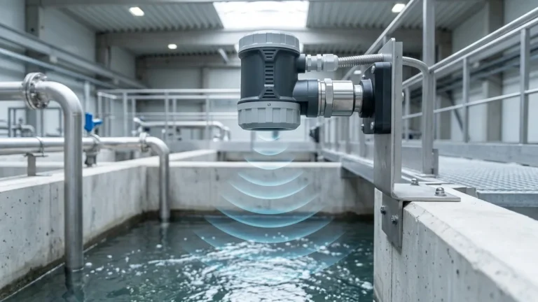
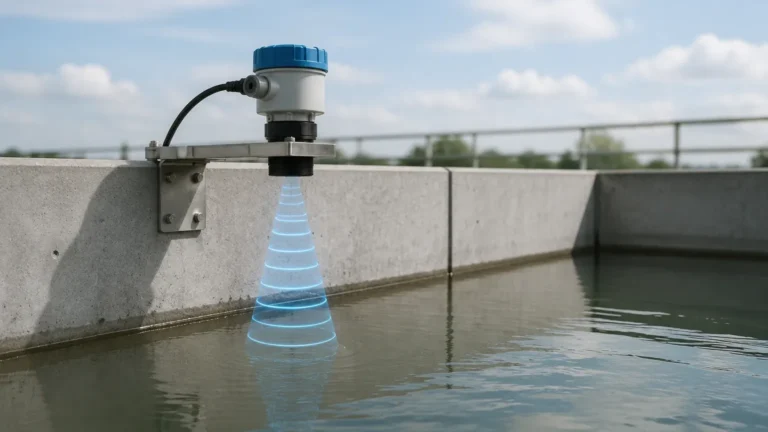
The sensor’s transducer contains a piezoelectric crystal that, when excited by an electrical pulse, vibrates at a high frequency (typically between 20 kHz and 200 kHz). This vibration generates an ultrasonic sound wave that travels through the air toward the target medium. Upon hitting the surface, the wave is reflected back to the transducer, which now acts as a receiver.
Calculating Distance
The internal electronics measure the time interval ($t$) between the emission of the pulse and the reception of the echo. Given the speed of sound in air ($c$), the distance ($D$) to the surface is calculated using the formula:
$$D = \frac{c \times t}{2}$$
Because the speed of sound is affected by air temperature, professional-grade sensors include an integrated temperature probe to perform real-time compensation. Once the distance is determined, the sensor’s microprocessor converts this value into a standardized ultrasonic level sensor output based on the user-defined range (Empty and Full points).
2. Common Types of Ultrasonic Level Sensor Output
Industrial ultrasonic sensors offer several output formats to ensure compatibility with different control architectures. These generally fall into three categories: analog, digital/switching, and communication protocols.
2.1 Analog Outputs (4-20mA and 0-10V)
The 4-20mA current loop is the global standard for analog signaling in process industries. Its popularity stems from several technical advantages:
* Noise Immunity: Current signals are significantly less susceptible to Electromagnetic Interference (EMI) than voltage signals, making them ideal for long cable runs in industrial environments.
* Fault Detection: A "live zero" (4mA) allows the system to distinguish between a zero-level measurement and a broken wire (0mA).
* Loop Powering: Many ultrasonic sensors are "two-wire" devices, meaning they draw their operating power directly from the 4-20mA loop, simplifying wiring requirements.
Voltage outputs, such as 0-5V or 0-10V, are less common in heavy industry but are frequently used in laboratory settings or with low-power IoT data loggers where cable distances are short.
2.2 Digital and Switching Outputs
Switching outputs are used for point-level detection rather than continuous measurement. These are typically used to trigger alarms or control pumps directly.
* Relay Outputs: Mechanical or solid-state relays that provide a dry contact for high-level or low-level alerts.
* Transistor Outputs (NPN/PNP): Fast-switching electronic outputs used for interfacing with high-speed digital inputs on a PLC.
2.3 Industrial Communication Protocols
Modern smart sensors often provide digital data bus outputs. These allow for the transmission of more than just the level value; they can provide diagnostic data, signal strength, and temperature readings.
* HART (Highway Addressable Remote Transducer): A hybrid protocol that superimposes a digital signal on top of a standard 4-20mA analog signal.
* Modbus RTU (RS485): A widely used serial communication protocol that allows for multi-drop configurations, where multiple sensors are connected to a single pair of wires.
* Profibus/PROFINET: Used in high-end automation environments requiring high-speed data exchange and integration with Siemens-based control systems.
3. Signal Processing and Output Calibration
The raw distance measurement must be scaled to the desired ultrasonic level sensor output range. This process involves defining the "Empty" (4mA) and "Full" (20mA) points within the sensor’s software.
Mapping the Range
In a typical tank application, the 4mA point is assigned to the maximum distance from the sensor (the bottom of the tank), while the 20mA point is assigned to the minimum distance (the highest liquid level). It is critical to account for the "Blanking Zone" (or Dead Zone)—the area immediately in front of the transducer where the sensor cannot accurately measure. If the liquid enters this zone, the output signal may become erratic or default to an error state.
Damping and Response Time
To prevent the output from fluctuating due to surface turbulence, splashing, or agitators, sensors use "damping" or averaging algorithms. A higher damping value (e.g., 10 seconds) results in a smoother output signal but a slower response to rapid level changes. For most industrial applications, a damping setting of 1 to 5 seconds provides a balance between stability and responsiveness.
4. Factors Influencing Output Accuracy
While the internal processing of the ultrasonic level sensor output is precise, external factors can introduce errors into the signal transmitted to the control room.
| Factor | Impact on Output | Mitigation Strategy |
| :— | :— | :— |
| Temperature Gradients | Changes the speed of sound, causing distance errors. | Use sensors with integrated temperature compensation. |
| Heavy Foam | Absorbs the ultrasonic pulse, leading to "Loss of Echo." | Consider radar level meters or stilling wells for foam-heavy liquids. |
| Vapor/Dust | High concentrations of steam or dust can attenuate the signal. | Select lower frequency sensors with higher power. |
| Tank Obstructions | Internal pipes or ladders can create false echoes. | Use "False Echo Suppression" software to mask fixed obstructions. |
| Electrical Noise | Induces interference in analog signal lines. | Use shielded twisted-pair cables and ensure proper grounding. |
5. Selection Guide: Matching Output to Application
Selecting the correct output configuration depends on the existing infrastructure and the required level of data granularity.
| Requirement | Recommended Output | Reason |
| :— | :— | :— |
| Basic continuous monitoring | 4-20mA (2-wire) | Cost-effective, industry-standard, easy to wire. |
| High/Low level alarms only | Relay / PNP Switch | Simple logic, no PLC scaling required. |
| Remote diagnostics & calibration | HART | Allows configuration over the signal wire. |
| Multiple sensors on one cable | Modbus RS485 | Reduces wiring costs for large tank farms. |
| High-speed automation | 4-20mA or PROFINET | Low latency and high reliability. |
6. Installation Considerations for Signal Integrity
To ensure the ultrasonic level sensor output remains accurate and reliable over time, proper installation is paramount.
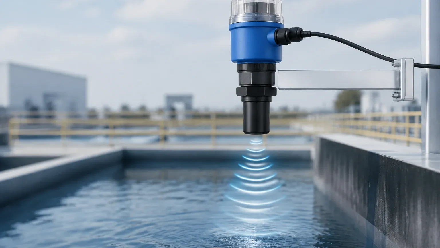
1. Perpendicularity: The sensor must be mounted perfectly perpendicular to the liquid surface. An angle of even a few degrees can cause the reflected signal to miss the transducer, resulting in a weak or lost output.
2. Avoid the Wall: Do not mount the sensor too close to the tank wall. The ultrasonic beam spreads as it travels (typically a 5° to 12° beam angle), and reflections from the wall can interfere with the primary echo.
3. Cable Shielding: Analog output cables should be shielded and separated from high-voltage power lines to prevent electromagnetic coupling. The shield should generally be grounded at only one end (usually the control cabinet) to avoid ground loops.
4. Power Supply Stability: Ensure the DC power supply (typically 24V DC) is stable. Voltage drops or ripples can manifest as noise on the 4-20mA output signal.
7. Limitations of Ultrasonic Output
While highly versatile, there are specific scenarios where the Ultrasonic Level Meters output may fail to provide reliable data:
* Vacuum Conditions: Sound waves cannot travel through a vacuum. In such cases, the sensor will fail to produce a valid output.
* High Pressure: Changes in air density at high pressures significantly affect the speed of sound beyond the capabilities of standard temperature compensation.
* Extreme Turbulence: If the surface is boiling or heavily agitated, the ultrasonic pulse may be scattered, leading to an intermittent output signal.
8. Troubleshooting Common Output Issues
"Frozen" Output (e.g., stuck at 4mA or 20mA)
This often indicates that the sensor has lost its echo and is holding the last known value or has defaulted to a fail-safe state. Check for obstructions or foam on the surface.
Fluctuating or "Jumpy" Signal
This is usually caused by electrical interference or surface turbulence. Increasing the damping (averaging) time in the sensor settings often resolves this. If the issue persists, check the integrity of the cable shielding.
Nonlinearity
If the output does not match the actual level linearly, ensure the tank shape is correctly programmed. For example, in horizontal cylindrical tanks, the relationship between level and volume is non-linear, and the sensor must be set to "Volume Mode" if volume output is required.
9. Frequently Asked Questions (FAQs)
Q: Can I use a 4-20mA output for distances over 500 meters?
A: While 4-20mA is robust, the resistance of the wire (loop impedance) becomes a factor over very long distances. For runs exceeding 300-500 meters, it is often better to use a digital protocol like Modbus RS485 or convert the signal to fiber optics.
Q: What is the difference between a 2-wire and 4-wire ultrasonic level sensor output?
A: A 2-wire sensor uses the same two wires for both power and the 4-20mA signal. A 4-wire sensor has two dedicated wires for power (often 220V AC or 24V DC) and two separate wires for the output signal. 4-wire sensors are typically used for high-power applications or when relays are included.
Q: How does the blanking zone affect my output?
A: If the liquid rises into the blanking zone (e.g., the top 0.3m of the tank), the sensor cannot process the echo. The output will typically jump to a pre-defined error value (like 22mA or 3.8mA) or stay at the 20mA limit.
Q: Is the output affected by changes in humidity?
A: Humidity has a very minor effect on the speed of sound compared to temperature. In most industrial applications, the error introduced by humidity is negligible and does not require additional compensation.
Conclusion
The ultrasonic level sensor output is the critical link between the physical process and the decision-making control system. By selecting the appropriate signal type—whether it be the robust 4-20mA analog loop, a simple relay switch, or a data-rich Modbus connection—engineers can ensure reliable and accurate level monitoring. Proper attention to calibration, installation geometry, and environmental factors will maximize the performance of Ultrasonic Level Meters in any industrial setting.