Ultrasonic Level Measurement Principle
In the realm of industrial automation and process control, accurate level monitoring is fundamental to operational efficiency, safety, and inventory management. Among the various technologies available, Ultrasonic Level Meters have emerged as a preferred solution for many applications due to their non-contact nature and versatility. Understanding the ultrasonic level measurement principle is essential for engineers and plant managers to correctly specify, install, and maintain these instruments in diverse environments ranging from water treatment facilities to chemical processing plants.
The Core Ultrasonic Level Measurement Principle
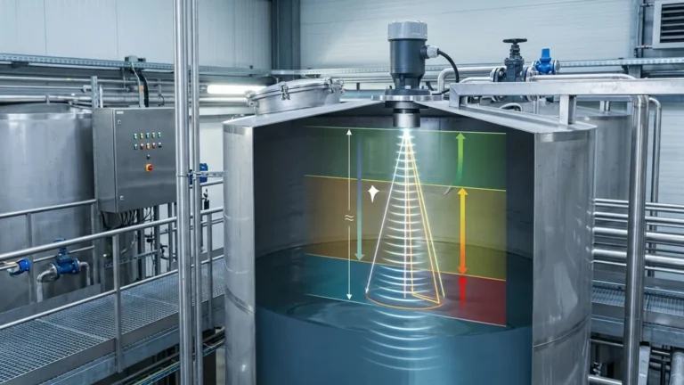
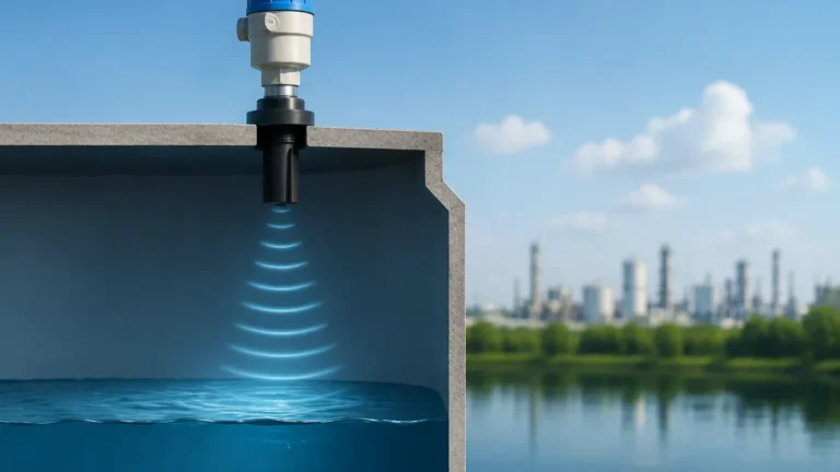
The fundamental ultrasonic level measurement principle is based on the "Time-of-Flight" (ToF) technology. This method involves measuring the time it takes for an ultrasonic pulse to travel from a sensor to the surface of the medium and back again.
1. Signal Emission and Reflection
An ultrasonic transducer, typically containing a piezoelectric crystal, converts electrical energy into mechanical energy in the form of high-frequency sound waves (ultrasound). These waves travel through the air or gas space above the material at the speed of sound. When the sound waves encounter a change in density—such as the interface between air and a liquid or solid surface—a portion of the energy is reflected back toward the sensor as an echo.
2. The Calculation Formula
The distance between the sensor and the material surface is calculated using a simple physical relationship:
D = (c × t) / 2
Where:
* D is the distance from the sensor to the material surface (meters).
* c is the velocity of sound in the medium, usually air (approximately 344 m/s at 20°C).
* t is the total elapsed time from pulse emission to echo reception (seconds).
Since the time measured represents a round trip (down and back), the result is divided by two. To determine the actual level (L) of the material in a tank, the measured distance (D) is subtracted from the total tank height or the sensor's installation height (H):
L = H – D
3. Signal Processing and Echo Filtering
Modern Ultrasonic Level Meters do not simply measure the first return signal. Industrial environments are often noisy or contain internal obstructions like ladders, agitators, or pipes. Advanced electronics utilize digital signal processing (DSP) to filter out "false echoes" caused by these obstructions, focusing only on the true reflection from the material surface. This process, often referred to as echo mapping or blanking, ensures high reliability even in complex tank geometries.
Key Components of an Ultrasonic System
To implement the ultrasonic level measurement principle effectively, a system typically comprises three main elements:
1. The Transducer: The "heart" of the meter, responsible for emitting and receiving the ultrasonic pulses. The frequency of the transducer (typically between 20 kHz and 80 kHz) determines the measuring range and the sensor's ability to penetrate dust or steam.
2. The Electronics/Transmitter: This unit controls the pulse timing, amplifies the returning echo, performs the distance calculation, and converts the result into a standardized output signal (such as 4-20mA, HART, or Modbus).
3. The Housing: Designed to protect the internal components from environmental factors. Depending on the application, housings may be made of plastic (for corrosive chemicals) or aluminum/stainless steel (for rugged industrial use).
Technical Selection Criteria
Choosing the right instrument requires matching the sensor specifications to the specific process conditions. Below is a practical selection table to guide the decision-making process.
| Feature | Consideration | Recommendation |
| :— | :— | :— |
| Measuring Range | Total height of the vessel or depth of the sump. | Select a sensor with a range 20% greater than the maximum required distance. |
| Medium State | Is it a liquid, slurry, or solid? | Liquids provide cleaner reflections; solids may require higher-power sensors due to uneven surfaces. |
| Chemical Properties | Is the medium corrosive or acidic? | Use PVDF or PTFE-faced transducers for chemical resistance. |
| Process Temperature | Speed of sound varies with temperature. | Ensure the meter has integrated temperature compensation. |
| Ambient Pressure | Ultrasonic waves require a medium (air/gas) to travel. | Standard meters operate near atmospheric pressure (0.7 to 3 bar). |
| Tank Internal Geometry | Presence of agitators, spray balls, or baffles. | Choose meters with advanced false-echo suppression software. |
| Power Supply | Loop-powered (2-wire) vs. External power (4-wire). | 2-wire is easier to install; 4-wire provides more power for long-range or difficult applications. |
Installation Considerations and Best Practices
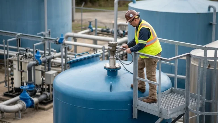
Even the most advanced meter will fail if the ultrasonic level measurement principle is undermined by poor installation. Adhering to the following guidelines is critical for accuracy:
The Blocking Distance (Dead Zone)
Every ultrasonic sensor has a "blocking distance" or "dead zone" immediately below the transducer face where it cannot measure. This occurs because the transducer cannot emit and receive simultaneously; it needs a few milliseconds to stop vibrating after the pulse is sent. If the material level rises into this zone, the meter will provide erratic readings. Always mount the sensor high enough to ensure the maximum level never enters the dead zone.
Mounting Location
* Avoid the Center: In rounded or conical tanks, mounting the sensor in the exact center can cause multiple reflections to converge, creating a "parabolic effect" that confuses the electronics.
* Stay Away from Inlets: Do not install the sensor directly above the fill stream. The falling material will interfere with the ultrasonic pulse and cause false readings.
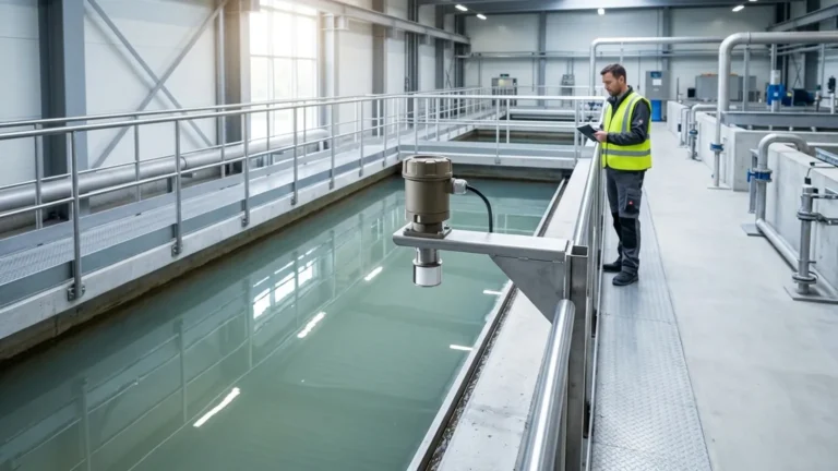
* Perpendicular Alignment: The transducer face must be perfectly parallel to the liquid surface. A tilt of even a few degrees can cause the reflected signal to miss the sensor entirely, especially at longer distances.
Beam Angle and Obstructions
The ultrasonic pulse spreads out in a cone shape (typically 5° to 12°). Ensure that no internal structures like ladders or pipes intersect this beam path. If obstructions are unavoidable, use a meter with software that can "map out" these static echoes.
Limitations and Environmental Factors
While highly versatile, the ultrasonic level measurement principle has physical limitations that must be acknowledged:
1. Vacuum Conditions: Sound waves cannot travel in a vacuum. Ultrasonic meters are unsuitable for vessels under full vacuum.
2. Heavy Foam: Dense, thick foam on a liquid surface acts as an acoustic absorber, soaking up the ultrasonic energy rather than reflecting it. In these cases, radar or hydrostatic sensors may be more appropriate.
3. High Dust and Vapor: While some dust is manageable, extremely heavy dust (in grain silos) or dense steam can attenuate the signal. High-frequency sensors are more susceptible to this than low-frequency ones.
4. Temperature Gradients: Since the speed of sound changes by approximately 0.17% per degree Celsius, significant temperature fluctuations between the sensor and the surface can cause errors if not compensated for by an internal or external temperature probe.
Frequently Asked Questions (FAQs)
Q: Can ultrasonic level meters be used for solids like sand or grain?
A: Yes, but with caveats. Solid surfaces are often angled (angle of repose) and less reflective than liquids. This usually requires a sensor with a higher power output and a lower frequency to ensure a reliable return signal.
Q: How does wind or air turbulence affect the measurement?
A: In outdoor applications or tanks with heavy ventilation, air movement can "blow" the ultrasonic pulse away or cause signal fluctuations. Using a stilling well or a sensor with a higher sampling rate can mitigate these effects.
Q: What is the typical accuracy of an ultrasonic level meter?
A: Most industrial-grade Ultrasonic Level Meters offer an accuracy of ±0.25% of the detected range or better, provided they are calibrated and installed correctly.
Q: Is calibration required frequently?
A: Unlike mechanical systems, ultrasonic meters have no moving parts to wear out. Once the initial "Empty" and "Full" points are set and the speed of sound is compensated for temperature, they are generally maintenance-free and do not require periodic re-calibration unless the process medium or gas composition changes significantly.
Summary for Engineering Specification
When applying the ultrasonic level measurement principle to a new project, engineers should confirm the following data points before final selection:
* The maximum and minimum distance to be measured.
* The chemical composition of the vapor space (to ensure the speed of sound constant is accurate).
* The minimum and maximum process temperatures.
* The presence of any potential acoustic absorbers like foam or heavy dust.
By respecting the physics of sound and following rigorous installation standards, ultrasonic technology provides a cost-effective, reliable, and low-maintenance solution for modern industrial level measurement needs.