Ultrasonic Water Level Measurement
Ultrasonic Water Level Measurement: A Technical Guide for Industrial Applications
In the landscape of industrial automation and environmental monitoring, accurate water level detection is fundamental to operational efficiency, safety, and regulatory compliance. Among the various technologies available, ultrasonic water level measurement has emerged as a preferred solution for engineers and facility managers due to its non-contact nature and versatility across diverse environments.
Whether managing municipal wastewater treatment plants, chemical storage facilities, or open-channel irrigation systems, selecting the right instrumentation requires a deep understanding of acoustic physics and process conditions. This article provides a comprehensive technical overview of Ultrasonic Level Meters, their operating principles, selection criteria, and best practices for installation in industrial water applications.
Understanding the Principles of Ultrasonic Level Measurement
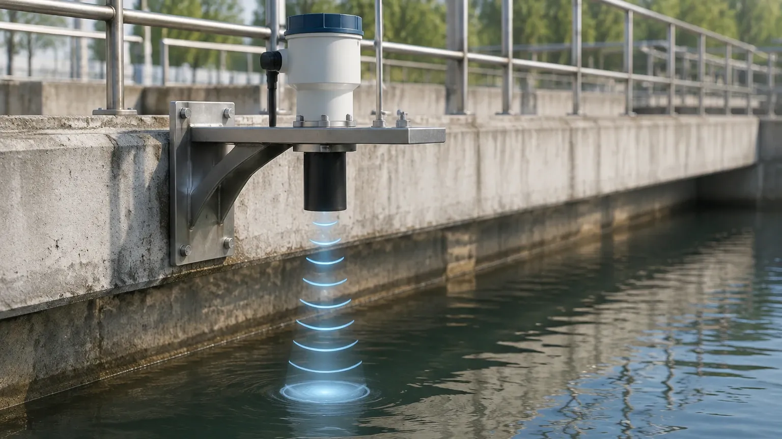
Ultrasonic measurement is based on the "Time-of-Flight" (ToF) principle. The instrument, typically mounted at the top of a vessel or above a water surface, contains a transducer that incorporates a piezoelectric crystal. When energized, this crystal vibrates at a high frequency, emitting a burst of ultrasonic sound waves—pulses that are generally above the range of human hearing (typically 20 kHz to 70 kHz).
The Measurement Cycle
1. Emission: The sensor sends a pulse toward the water surface.
2. Reflection: The sound wave travels through the air, hits the surface of the water, and reflects back toward the sensor.
3. Detection: The transducer receives the reflected echo.
4. Calculation: The internal microprocessor calculates the time elapsed between emission and reception.
The distance ($D$) from the sensor to the water surface is calculated using the formula:
$D = (c \times t) / 2$
Where:
* $c$ is the speed of sound in the medium (air).
* $t$ is the total time elapsed (the round trip).
By knowing the total height of the tank or the distance to the bottom of a channel, the device can then determine the actual water level. Modern instruments like those from Welk integrate sophisticated signal processing algorithms to filter out "false echoes" caused by internal tank structures, agitators, or localized turbulence.
The "Dead Zone" (Blocking Distance)
Every ultrasonic sensor has a characteristic known as the "dead zone" or blocking distance. This is a small area directly beneath the transducer face where the sensor cannot accurately measure. Because the transducer cannot switch from "transmit" to "receive" instantaneously, any reflection that returns before the transducer is ready to receive is ignored. This typically ranges from 0.2 meters (approx. 8 inches) to 0.5 meters (approx. 20 inches) depending on the frequency of the device.
Key Advantages for Industrial Water Management
Ultrasonic technology offers several distinct advantages over contact-based methods such as hydrostatic pressure sensors or float switches:
* Non-Contact Measurement: Since the sensor never touches the water, it is immune to corrosion, scaling, and fouling from debris or biological growth. This is particularly critical in wastewater and chemical processing.
* Low Maintenance: With no moving parts to wear out or mechanical components to clean, ultrasonic water level measurement significantly reduces the Total Cost of Ownership (TCO).
* High Accuracy: In standard atmospheric conditions, ultrasonic sensors provide high precision, often within ±0.25% of the measured range.
* Versatility: These meters can be used in both liquid level measurement and open-channel flow measurement (when paired with flumes or weirs).
Critical Factors in Ultrasonic Water Level Measurement Selection
Selecting the appropriate instrument requires balancing technical specifications with the specific environmental conditions of the site. Engineers should evaluate the following parameters before procurement.
Selection Table: Technical Specifications Comparison
| Feature | Standard Water Tank | Wastewater/Sump | Chemical Storage |
| :— | :— | :— | :— |
| Measuring Range | 0–10m (0–33ft) | 0–5m (0–16ft) | 0–15m (0–49ft) |
| Accuracy | ±0.5% F.S. | ±0.25% F.S. | ±0.25% F.S. |
| Housing Material | ABS / Plastic | PVDF / Reinforced Plastic | PTFE / PVDF |
| Output Signal | 4-20mA / RS485 | 4-20mA / HART | 4-20mA / Modbus |
| Beam Angle | 8° – 12° | 6° – 10° | 5° – 8° |
| Protection Rating| IP65 | IP67 / IP68 | IP67 / Explosion Proof |
Beam Angle and Obstructions
The beam angle is the conical spread of the ultrasonic pulse. A narrower beam angle is generally preferred for narrow tanks or vessels with internal obstructions (like ladders or pipes). If the beam hits an obstruction before reaching the water surface, it will return a false high-level reading. Welk’s advanced Ultrasonic Level Meters utilize echo-mapping software to identify and ignore these fixed obstructions.
Temperature Compensation
The speed of sound ($c$) is not constant; it varies with air temperature. A change of 1°C can result in a 0.17% error in distance measurement. Therefore, industrial-grade sensors must include an integrated temperature sensor to provide real-time compensation. For applications with significant temperature gradients between the water surface and the sensor, external temperature probes may be required for higher accuracy.
Installation Best Practices for Accurate Data
Proper installation is the most critical factor in ensuring the reliability of ultrasonic water level measurement. Even the most advanced sensor will fail if positioned incorrectly.
1. Positioning and Clearance
* Avoid the Center: In cylindrical tanks with domed tops, do not install the sensor in the exact center. The dome can act as a parabolic reflector, concentrating multiple echoes and confusing the sensor.
* The 1/6th Rule: A common engineering rule of thumb is to install the sensor at a distance from the tank wall equal to 1/6th of the tank's diameter.
* Stay Away from Inlets: Never install the sensor directly above the fill stream. The falling water creates turbulence and air bubbles that scatter the ultrasonic signal.
2. Alignment
The transducer face must be perfectly parallel to the water surface. If the sensor is tilted, the ultrasonic pulse will reflect away from the transducer rather than back toward it, resulting in a "Lost Echo" error.
3. Standoff Pipes (Still Wells)
In applications with heavy surface foam or extreme turbulence, a standoff pipe or stilling well can be used. This pipe acts as a guide for the ultrasonic pulse, providing a calm surface for measurement. However, the pipe's interior must be smooth and free of burrs or joints that could create false reflections.
Environmental Limitations and Mitigation Strategies
While ultrasonic sensors are robust, certain physical conditions can interfere with sound wave propagation.
* Heavy Foam: Thick, dense foam absorbs ultrasonic pulses rather than reflecting them. If the application involves heavy surfactants or foaming agents, a radar level meter or a hydrostatic transmitter may be a better choice.
* Vapor and Steam: High concentrations of steam or chemical vapors can change the density of the air medium, significantly affecting the speed of sound. In these cases, the error may exceed the acceptable tolerance unless specialized compensation is used.
* Vacuum or High Pressure: Ultrasonic waves require a medium (air or gas) to travel. They cannot function in a vacuum. Similarly, very high pressure alters the air density to a point where standard sound speed calibrations no longer apply.
* Dust: While light dust is manageable, extremely heavy dust (common in dry bulk but less so in water applications) can attenuate the signal.
Maintenance and Troubleshooting for Long-Term Reliability
Although ultrasonic water level measurement systems are low-maintenance, a routine inspection schedule ensures longevity:
1. Transducer Cleaning: In high-humidity environments, condensation can form on the transducer face. While many Welk sensors are designed to shed droplets, a periodic wipe with a soft cloth prevents mineral buildup.
2. Check Seals: Ensure that cable glands and housing covers are tightened to maintain the IP rating, preventing moisture ingress into the electronics.
3. Signal Strength Monitoring: Most modern meters provide a "Signal-to-Noise Ratio" (SNR) or signal strength indicator. A gradual decline in signal strength may indicate a buildup on the sensor or changing process conditions (like increasing foam).
Troubleshooting Common Issues
* Reading stays at maximum: This often indicates the sensor is measuring into the "Dead Zone." Raise the sensor or lower the maximum fill level.
* Reading jumps erratically: This is usually caused by electrical interference or the sensor picking up reflections from an agitator. Ensure shielded cabling is used and check the "False Echo Suppression" settings.
* "Lost Echo" during filling: This is typically caused by heavy turbulence or dust. Adjust the damping or response time settings in the transmitter menu.
Conclusion
Ultrasonic water level measurement remains a cornerstone of industrial process control. By understanding the physics of sound propagation and adhering to strict installation guidelines, engineers can achieve highly reliable and maintenance-free level monitoring. When selecting a system, always consider the specific chemistry of the water, the physical dimensions of the vessel, and the potential for environmental interference. For complex applications, consulting with a specialist to review Ultrasonic Level Meters specifications ensures that the chosen technology aligns with the long-term operational goals of the facility.
Frequently Asked Questions (FAQ)
Q: Can ultrasonic sensors measure the level of solids?
A: Yes, but with limitations. Solids like grain or sand have an angle of repose that reflects the sound wave away from the sensor. A higher-power transducer and careful aiming are required compared to liquid applications.
Q: How does wind affect open-channel ultrasonic measurement?
A: Strong wind can "blow" the ultrasonic pulse away or create surface ripples. In outdoor installations, using a sunshade/windshield and selecting a sensor with a higher signal-to-noise ratio is recommended.
Q: What is the maximum range for ultrasonic water level measurement?
A: Most industrial sensors range from 5 meters (16ft) to 30 meters (98ft). For distances beyond 30 meters, radar technology is generally more effective due to the attenuation of sound waves over long distances in air.
Q: Is the 4-20mA signal affected by the distance between the sensor and the controller?
A: The 4-20mA analog signal is robust and can typically be transmitted up to 1,000 meters (3,280ft) using twisted-pair shielded cable without significant signal loss, making it ideal for large-scale industrial plants.