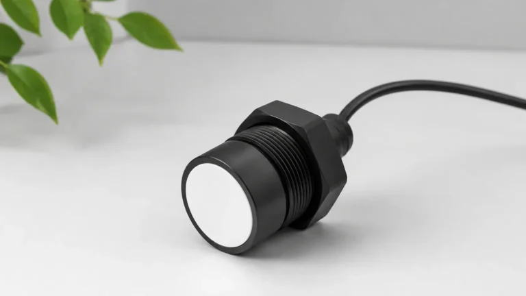
Ultrasonic Level Sensor Rs485
Ultrasonic Level Sensor RS485: A Technical Guide for Industrial Integration
In the landscape of industrial automation, the ability to monitor liquid and solid levels with precision is fundamental to operational efficiency and safety. Among the various technologies available, ultrasonic level measurement has emerged as a preferred non-contact method for a wide range of applications, from water treatment to chemical processing. When integrated with digital communication interfaces, specifically the ultrasonic level sensor rs485, these instruments offer enhanced data integrity, remote configuration capabilities, and seamless integration into modern SCADA and PLC systems.
As a professional manufacturer, Welk provides advanced Ultrasonic Level Meters designed to meet the rigorous demands of industrial environments. This guide explores the technical principles, selection criteria, and installation best practices for RS485-enabled ultrasonic sensors.
Measurement Principles of Ultrasonic Technology
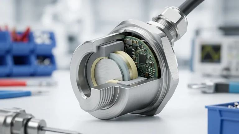
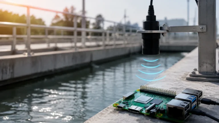
Ultrasonic level measurement is based on the "Time of Flight" (ToF) principle. The sensor’s transducer emits a high-frequency acoustic pulse that travels through the air toward the surface of the medium being measured. When the pulse hits the surface, it reflects back to the transducer, which then acts as a receiver.
The Calculation of Distance
The internal electronics of the sensor measure the time interval ($t$) between the emission of the pulse and the reception of the echo. Given that the speed of sound ($c$) in air is approximately 344 meters per second at 20°C, the distance ($D$) between the sensor and the material surface is calculated using the formula:
$$D = \frac{c \times t}{2}$$
Since the installation height ($H$) of the sensor is known, the actual level ($L$) of the material is determined by subtracting the measured distance from the total height ($L = H – D$).
Frequency and Range
The operating frequency of the ultrasonic pulse typically ranges from 20 kHz to 80 kHz. Lower frequencies (e.g., 20-30 kHz) are used for long-range measurements (up to 30 or 40 meters) because they suffer less attenuation in the air. Higher frequencies (e.g., 60-80 kHz) provide better resolution and smaller "blind zones" but are limited to shorter ranges, typically under 10 meters.
The Role of RS485 in Level Measurement
While traditional 4-20mA analog signals remain common, the ultrasonic level sensor rs485 has become the standard for digital industrial networking. RS485 is a physical layer standard that defines the electrical characteristics of drivers and receivers for use in serial communications systems.
Advantages of RS485 Modbus RTU
Most industrial ultrasonic sensors utilize the Modbus RTU protocol over the RS485 interface. This combination offers several distinct advantages:
1. Noise Immunity: RS485 uses differential signaling, which makes it highly resistant to electromagnetic interference (EMI) commonly found in industrial plants with large motors and variable frequency drives (VFDs).
2. Multi-drop Capability: A single RS485 bus can support up to 32 devices (or more with repeaters) on the same twisted-pair wire, significantly reducing cabling costs compared to point-to-point analog wiring.
3. Long Distance: Digital signals can be transmitted reliably over distances up to 1,200 meters without the signal degradation associated with voltage drops in long analog loops.
4. Rich Data Sets: Beyond the primary level measurement, an RS485 connection allows the system to retrieve diagnostic data, such as signal strength, internal temperature, and error codes, which are essential for predictive maintenance.
Key Evaluation Criteria for Selection
When selecting an ultrasonic level sensor rs485, engineers must evaluate several technical parameters to ensure the device is compatible with the specific process environment.
1. Measurement Range and Blind Zone
Every ultrasonic sensor has a "blind zone" (also known as the blocking distance) directly beneath the transducer where measurements are impossible. This is caused by the time required for the transducer to stop vibrating after emitting a pulse before it can begin listening for the return echo. A typical blind zone ranges from 0.2m to 0.5m depending on the frequency.
2. Beam Angle
The ultrasonic pulse spreads out in a cone shape. The beam angle (usually between 5° and 12°) determines the footprint of the signal at a given distance. If the beam is too wide, it may hit tank walls, ladders, or agitators, resulting in false echoes.
3. Material Compatibility
For corrosive environments, such as acid tanks or wastewater treatment plants, the wetted parts of the sensor (the transducer face) must be made of chemically resistant materials like PVDF (Polyvinylidene fluoride) or PTFE (Polytetrafluoroethylene).
4. Environmental Compensation
The speed of sound varies with air temperature ($c \approx 331.4 + 0.6 \times T$). Therefore, an integrated temperature sensor is mandatory for accurate measurement. High-quality Ultrasonic Level Meters include automatic temperature compensation algorithms.
Practical Selection Table
| Feature | Standard Liquid Sensor | Long-Range Solids Sensor | Chemical-Resistant Sensor |
| :— | :— | :— | :— |
| Max Range | 10 meters | 30 meters | 15 meters |
| Blind Zone | 0.25 meters | 0.6 meters | 0.35 meters |
| Communication | RS485 / Modbus RTU | RS485 / Modbus RTU | RS485 / Modbus RTU |
| Beam Angle | 8° – 10° | 5° – 6° | 8° – 12° |
| Housing Material | ABS / Nylon | Aluminum Alloy | PVDF / PTFE |
| Accuracy | ±0.25% of FS | ±0.5% of FS | ±0.25% of FS |
| Protection | IP67 | IP68 | IP68 / Ex-proof |
Installation Considerations and Best Practices
Proper installation is critical for the reliable performance of an ultrasonic level sensor rs485. Incorrect mounting is the most common cause of signal loss or inaccurate readings.
Mounting Position
* Avoid the Center: In cylindrical tanks, do not mount the sensor in the exact center, as this can create a focal point for multiple reflections, leading to "ghost" signals.
* Distance from Wall: The sensor should be mounted at a distance from the tank wall that is at least 1/6th of the tank diameter to prevent the ultrasonic beam from reflecting off the wall surface.
* Perpendicularity: The transducer face must be perfectly parallel to the liquid surface. A deviation of even a few degrees can cause the reflected signal to miss the receiver.
Obstruction Management
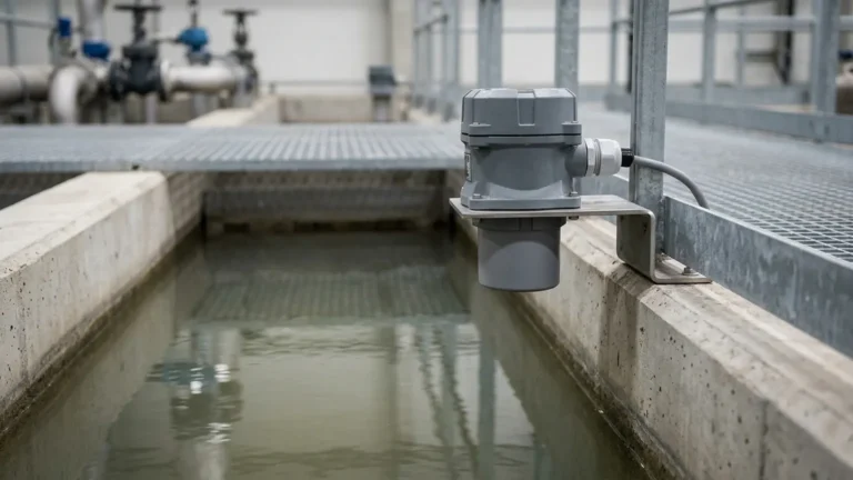
The path between the sensor and the maximum liquid level must be clear of obstructions. If internal structures like pipes or agitators are present, they must be outside the beam cone. In cases where obstructions are unavoidable, many Welk sensors offer "False Echo Suppression" software, allowing the user to map out and ignore static reflections.
RS485 Wiring Guidelines
* Shielded Twisted Pair: Always use shielded twisted pair (STP) cable for RS485 communication to minimize noise.
* Termination Resistors: For long cable runs, a 120-ohm termination resistor should be placed at both ends of the bus to prevent signal reflections.
* Grounding: The shield should be grounded at only one point (usually the PLC/Controller side) to avoid ground loops.
Limitations and Application Constraints
While highly versatile, ultrasonic technology is not a universal solution. Engineers should be aware of the following limitations:
1. Vacuum Conditions: Sound waves require a medium (air or gas) to travel. Therefore, ultrasonic sensors cannot function in a vacuum.
2. High Pressure: Extreme pressure changes the density of the air, affecting the speed of sound beyond what standard temperature compensation can handle. Most ultrasonic meters are limited to pressures below 3 bar (0.3 MPa).
3. Heavy Foam: Dense foam on the surface of a liquid can absorb the ultrasonic pulse rather than reflecting it, leading to a "Loss of Echo" error.
4. Dust and Vapor: While light dust is manageable, extremely heavy dust (in silos) or thick steam can scatter the signal. In such cases, radar level meters may be a more appropriate choice.
Maintenance and Troubleshooting
One of the primary benefits of the ultrasonic level sensor rs485 is the ability to perform remote diagnostics. If the system reports an error, the following steps are recommended:
* Check for Transducer Buildup: In wastewater or chemical applications, condensation or material buildup on the transducer face can dampen the signal. Regular cleaning with a soft cloth is recommended.
* Verify Power Supply: RS485 sensors often require a stable 24V DC power supply. Voltage drops can cause intermittent communication failures.
* Monitor Signal Strength: Using the Modbus interface, check the "Echo Strength" register. A declining trend may indicate increasing foam or a misalignment of the sensor.
Frequently Asked Questions (FAQ)
Q: Can an ultrasonic level sensor rs485 measure solids like grain or sand?
A: Yes, but the range is typically reduced by 50% compared to liquids because solids absorb more sound and the surface is often uneven, scattering the reflection.
Q: How do I integrate the sensor into my existing PLC?
A: You will need to configure the PLC as a Modbus Master and assign a unique Slave ID to the sensor. The sensor’s manual will provide a register map for level, distance, and temperature data.
Q: What happens if the liquid level enters the blind zone?
A: The sensor will output an error code or a default value (often the maximum or minimum range). It is essential to mount the sensor high enough so that the maximum possible liquid level never reaches the blind zone.
Conclusion
The ultrasonic level sensor rs485 represents a robust and cost-effective solution for modern industrial level monitoring. By combining the non-contact advantages of ultrasonic technology with the reliability of digital RS485 communication, Welk provides tools that empower engineers to achieve higher precision and better data integration. When selecting a device, careful consideration of the measurement environment, beam angles, and installation geometry will ensure long-term, maintenance-free operation. For more specialized requirements or detailed product specifications, exploring the full range of Ultrasonic Level Meters is the first step toward optimizing your process control system.