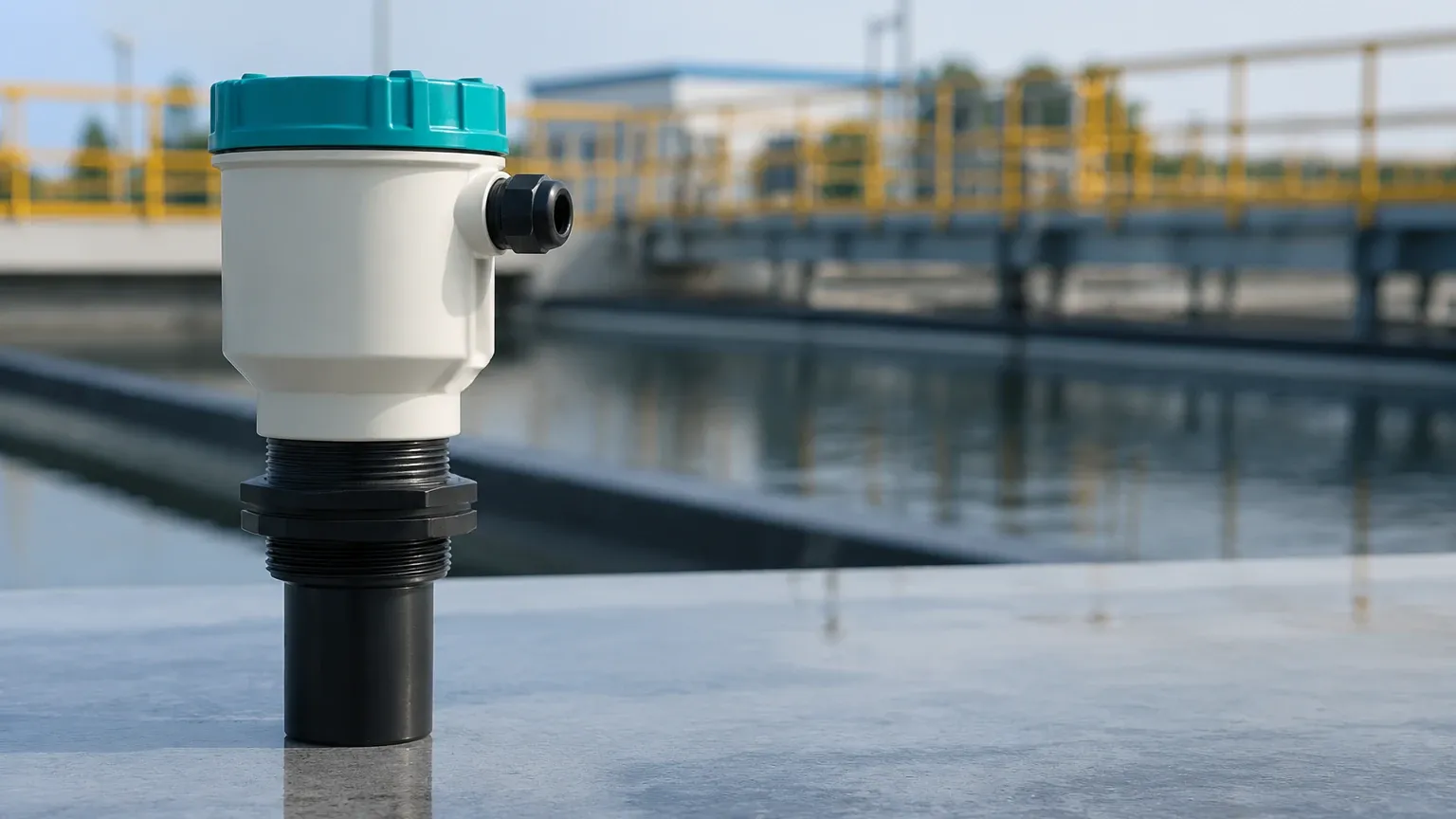
Ultrasonic Level Meter Siemens
Ultrasonic Level Meter Siemens: A Technical Guide for Industrial Applications
In the landscape of industrial process control, non-contact level measurement has become the preferred standard for many liquid and solid storage applications. Among the various technologies available, ultrasonic measurement remains a dominant choice due to its balance of accuracy, reliability, and cost-effectiveness. For many engineers and procurement specialists, the ultrasonic level meter Siemens series—specifically the SITRANS line—serves as a primary reference point for performance and durability. However, selecting the right instrument requires a deep understanding of the underlying physics, application constraints, and the specific features that differentiate high-end industrial sensors.
This guide explores the technical principles of ultrasonic measurement, evaluates the criteria for selecting high-performance Ultrasonic Level Meters, and provides a practical framework for integrating these devices into modern industrial workflows.
Understanding Ultrasonic Measurement Principles
Before selecting a specific model, such as an ultrasonic level meter Siemens SITRANS Probe LU240, it is essential to understand how the technology interacts with the process medium. Ultrasonic level sensors operate on the "Time-of-Flight" (ToF) principle.
The Transducer and Pulse Generation
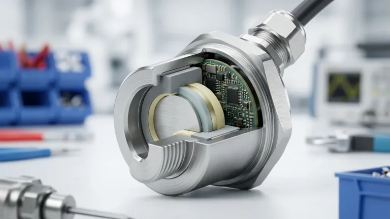
An ultrasonic sensor contains a piezoelectric crystal that converts electrical energy into mechanical vibrations. These vibrations create high-frequency sound waves (typically between 20 kHz and 200 kHz) that are emitted in pulses toward the material surface.
Reflection and Detection
When the sound wave hits the surface of the medium—whether it is water, a chemical solution, or a solid—it reflects back toward the sensor. The transducer then acts as a microphone, detecting the returning echo. The instrument’s internal processor measures the time interval between the emission of the pulse and the reception of the echo.
The Calculation
The distance from the sensor to the material surface (D) is calculated using the formula:
D = (c × t) / 2
Where:
* c is the speed of sound in the medium (usually air).
* t is the measured time for the round trip.
Since the height of the vessel (H) is known, the actual level (L) is determined by subtracting the distance (D) from the total height: L = H – D.
Signal Processing and "Sonic Intelligence"
One of the reasons the ultrasonic level meter Siemens brand is highly regarded is its proprietary signal processing, often referred to as "Sonic Intelligence." This software filters out false echoes caused by internal tank obstructions like ladders, agitators, or structural beams. When evaluating alternatives, such as those provided by Welk, ensuring robust echo processing is critical for maintaining accuracy in complex vessel geometries.
Key Evaluation Criteria for Industrial Applications
When specifying an ultrasonic level meter, several technical factors must be confirmed to ensure the device will perform under site-specific conditions.
1. Measurement Range and Blocking Distance
Every ultrasonic sensor has a "dead zone" or blocking distance immediately below the transducer face (typically 0.25m to 0.45m). In this zone, the sensor cannot accurately measure because the transducer is still vibrating from the pulse emission when the echo returns.
* Short Range: 0.25m to 6m (Ideal for small tanks and sumps).
* Long Range: Up to 30m or 60m (Required for large silos or deep wells).
2. Environmental Conditions: Temperature and Pressure
The speed of sound is highly dependent on air temperature. A change of 1°C can result in a 0.17% error in distance measurement. Professional-grade Ultrasonic Level Meters must include integrated temperature compensation. Furthermore, ultrasonic waves do not travel through a vacuum and are attenuated in high-pressure environments, typically limiting their use to atmospheric or near-atmospheric pressures (up to 3 bar).
3. Material Characteristics
* Liquids: Generally provide an excellent reflective surface. However, heavy foam can absorb the ultrasonic pulse, leading to signal loss.
* Solids: Powders and granules often have an irregular surface that scatters the sound wave. For these applications, high-power transducers and specialized aiming flanges are necessary.
4. Communication and Integration
Modern B2B operations require seamless integration with PLC and SCADA systems. Common requirements include:
* 4-20 mA Loop Power: The standard for most industrial installations.
* HART Protocol: Allows for remote configuration and advanced diagnostics.
* Modbus RTU / Profibus: Used for digital networking in automated plants.
Technical Selection Table: Ultrasonic Level Meter Siemens vs. Industrial Standards
The following table outlines the typical specifications found in the Siemens SITRANS series and comparable professional industrial level meters.
| Feature | SITRANS Probe LU240 (Standard) | Welk Industrial Series | High-Performance Multi-Ranger |
| :— | :— | :— | :— |
| Measurement Range | 3m, 6m, 12m | 5m, 10m, 15m | Up to 60m |
| Accuracy | ± 0.15% of range | ± 0.2% to 0.5% | ± 0.1% |
| Beam Angle | 10 degrees | 8 to 12 degrees | 5 degrees (Narrow) |
| Operating Temp | -40°C to +85°C | -20°C to +70°C | -40°C to +150°C |
| Output | 4-20 mA, HART | 4-20 mA, Modbus | Profibus, Relay Outputs |
| Enclosure Rating | IP66 / IP68 | IP65 / IP67 | IP68 |
Practical Installation Considerations
Correct installation is the most significant factor in preventing measurement errors. Even a premium ultrasonic level meter Siemens unit will fail if positioned incorrectly.
Positioning the Sensor
* Avoid the Center: In cylindrical tanks, do not mount the sensor in the exact center, as this can create multiple reflections that confuse the processor.
* Stay Away from Inlets: Ensure the sensor is not placed directly over the filling stream. Turbulence and falling material will disrupt the signal.
* Perpendicular Alignment: The transducer face must be perfectly parallel to the liquid surface. A tilt of just a few degrees can cause the echo to miss the receiver entirely.
Mounting and Standpipes
If a standpipe is used to mount the sensor, the interior of the pipe must be smooth and free of burrs or welds. The diameter of the pipe should be large enough to prevent the ultrasonic beam from hitting the pipe walls before reaching the medium. Generally, a 4-inch (100mm) pipe is recommended for most standard sensors.
Beam Angle Clearance
Consider the "beam angle" as a cone originating from the sensor. Any obstruction within this cone (ladders, pipes, or wall protrusions) will generate a false echo. If obstructions are unavoidable, ensure the device features "False Echo Suppression" software to map out these static reflections.
Limitations and Common Risks
While ultrasonic technology is versatile, it is not a universal solution. Engineers should be aware of the following risks:
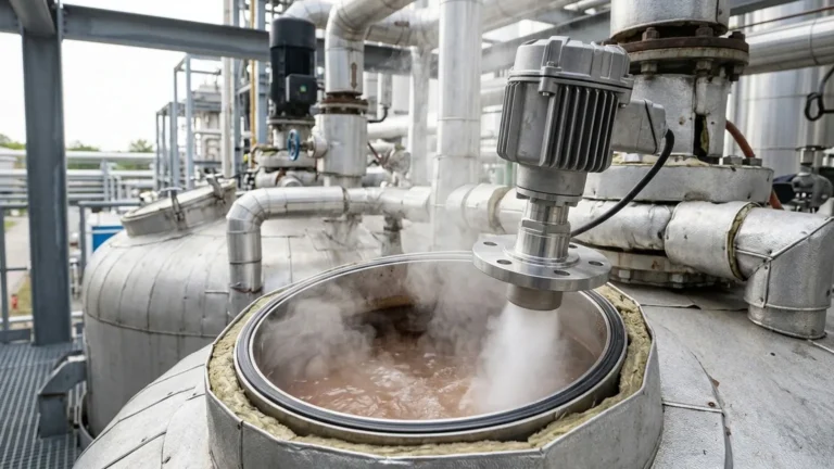
1. Vapor and Steam: High concentrations of steam or chemical vapors can change the composition of the air, altering the speed of sound and causing significant measurement errors.
2. Heavy Dust: In solid applications (like cement or flour), heavy dust during the filling process can attenuate the ultrasonic signal, leading to a "Loss of Echo" (LOE) condition.
3. Vacuum Conditions: Because sound requires a medium (air/gas) to travel, ultrasonic meters cannot function in a vacuum.
4. Surface Turbulence: Rapidly agitating liquids or boiling surfaces can scatter the signal. In these cases, a stilling well or a transition to radar level measurement might be required.
Why Choose Professional Industrial Solutions?
For projects requiring high reliability, such as municipal water treatment or chemical storage, the choice often comes down to the support and customization available. While an ultrasonic level meter Siemens offers a globally recognized standard, manufacturers like Welk provide specialized OEM/ODM services that allow for tailored sensor configurations, specific communication protocols, and cost-effective scaling for large-scale industrial automation projects.
Reliable level measurement reduces the risk of tank overfills, protects pumps from dry running, and ensures accurate inventory management. By following strict quality control and advanced signal processing techniques, modern ultrasonic sensors provide a maintenance-free alternative to mechanical floats and pressure transmitters.
Frequently Asked Questions (FAQ)
What is the difference between ultrasonic and radar level meters?
Ultrasonic meters use sound waves and are generally more cost-effective for water-based applications and simple liquids. Radar meters use electromagnetic waves, which are unaffected by temperature fluctuations, vacuum, or high pressure, making them better suited for extreme process conditions.
Can an ultrasonic level meter measure the level of foam?
Generally, no. Most foams are porous and absorb the sound energy rather than reflecting it. If foam is present, the sensor may report a "Loss of Echo" or measure the top of the foam layer rather than the liquid level. Radar or hydrostatic transmitters are often preferred for foaming liquids.
How often do ultrasonic sensors need calibration?
Once calibrated to the tank dimensions during commissioning, ultrasonic sensors typically do not require routine recalibration because they have no moving parts. However, periodic cleaning of the transducer face may be necessary if the environment is prone to condensation or material buildup.
Is the Siemens SITRANS Probe LU240 suitable for hazardous areas?
Yes, many models in the Siemens SITRANS range, as well as specialized industrial sensors from Welk, are available with ATEX, IECEx, or FM certifications for use in explosive atmospheres (Zone 0, 1, or 2).
How do I handle a "Loss of Echo" (LOE) error?
First, check for obstructions in the beam path or heavy turbulence on the surface. Ensure the transducer face is clean and the sensor is mounted perpendicular to the surface. If the problem persists, you may need to increase the pulse power or adjust the sensitivity settings in the device software.
For more information on selecting the right technology for your specific application, Review product options and application support to ensure your facility maintains peak operational efficiency.