Ultrasonic Meter Run
Ultrasonic Meter Run
In the landscape of industrial process control, the accuracy of level and flow measurement is heavily dependent on the physical environment in which the instrument operates. For engineers and plant managers, the concept of the ultrasonic meter run is a critical factor in ensuring that Ultrasonic Level Meters provide reliable data. While often discussed in the context of flow measurement, the principles of a "meter run"—the specific configuration of piping and mounting—are equally vital for non-contact level sensing applications in tanks, basins, and open channels.
Welk, a professional manufacturer of industrial level measurement instruments, provides this guide to help technical teams optimize their installations. By understanding the relationship between the ultrasonic signal and the physical path it travels, users can eliminate common errors such as false echoes, signal attenuation, and turbulence-induced fluctuations.
Understanding the Principles of Ultrasonic Level Meters
Before detailing the specifics of an ultrasonic meter run, it is essential to understand how these instruments function. Ultrasonic sensors operate on the "Time-of-Flight" (ToF) principle. The transducer emits a high-frequency sound pulse (typically between 20 kHz and 200 kHz) that travels through the air or gas space toward the surface of the medium.
Upon hitting the surface, the pulse is reflected back to the transducer. The instrument measures the time interval between the emission and the reception of the echo. The distance ($D$) is calculated using the formula:
$$D = \frac{v \cdot t}{2}$$
Where:
* $v$ is the speed of sound in the medium (approx. 343 m/s in air at 20°C).
* $t$ is the total time for the pulse to travel to the surface and back.
Because the speed of sound is affected by air temperature, Welk ultrasonic sensors include integrated temperature compensation to maintain accuracy across varying environmental conditions. However, the physical path—the meter run—must remain clear of obstructions to ensure the sensor "sees" only the intended target.
Defining the Ultrasonic Meter Run in Industrial Applications
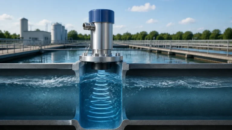
In technical terms, an ultrasonic meter run refers to the controlled environment through which the ultrasonic wave propagates. In level measurement, this often involves the use of standpipes, stilling wells, or specific nozzle configurations designed to guide the signal and protect it from external interference.
The Role of Stilling Wells and Standpipes
For applications involving turbulent surfaces, foam, or internal tank obstructions (such as agitators or heating coils), a stilling well acts as the meter run. This is a vertical pipe that extends into the liquid, providing a calm surface for the ultrasonic pulse to reflect from.
Key benefits of a properly designed ultrasonic meter run include:
1. Signal Isolation: It prevents the beam from hitting internal tank structures.
2. Surface Stabilization: It eliminates waves and ripples caused by mixers or filling processes.
3. Foam Mitigation: While ultrasonic waves struggle with heavy foam, a stilling well can provide a clear liquid surface for measurement.
Design Considerations for an Effective Ultrasonic Meter Run
When designing the installation path for Ultrasonic Level Meters, several engineering factors must be addressed to maintain signal integrity.
1. Beam Angle and Spread
Every ultrasonic transducer has a specific beam angle, usually ranging from 5° to 12°. As the distance increases, the diameter of the ultrasonic footprint expands. The meter run must be wide enough to accommodate this spread without the beam touching the walls of the pipe or the tank nozzle. If the beam hits a side wall, it creates a "false echo" that the sensor may mistake for the actual liquid level.
2. The Dead Zone (Blanking Distance)
All ultrasonic sensors have a "dead zone" or blanking distance directly beneath the transducer face (typically 0.2 m to 0.5 m, depending on the model). In a meter run configuration, the sensor must be mounted high enough so that the maximum liquid level never enters this zone. If the liquid enters the dead zone, the sensor will fail to provide an accurate reading.
3. Nozzle Geometry
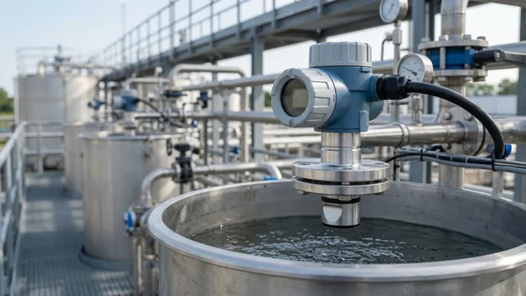
If the sensor is mounted on a nozzle, the height and diameter of that nozzle are part of the ultrasonic meter run. A nozzle that is too narrow or too long will cause internal reflections. As a general rule, the inner surface of the nozzle should be smooth and free of burrs or weld seams.
| Nozzle Diameter (mm) | Maximum Recommended Nozzle Height (mm) |
| :— | :— |
| 50 (2") | 100 |
| 80 (3") | 150 |
| 100 (4") | 200 |
| 150 (6") | 300 |
Selection Criteria for Ultrasonic Level Sensors
Choosing the right instrument for your specific ultrasonic meter run depends on the chemical nature of the medium, the required range, and the environmental conditions. Welk offers a variety of configurations to suit diverse industrial needs.
| Feature | Standard Industrial Series | High-Precision Series | Chemical Resistant Series |
| :— | :— | :— | :— |
| Measuring Range | 0.4 m – 10 m | 0.3 m – 15 m | 0.4 m – 12 m |
| Accuracy | ±0.5% FS | ±0.25% FS | ±0.5% FS |
| Beam Angle | 10° – 12° | 6° – 9° | 10° |
| Material | ABS/PVC | PVDF/Stainless Steel | PTFE/PVDF |
| Output | 4-20mA / RS485 | 4-20mA / Hart / RS485 | 4-20mA / RS485 |
| Application | Water treatment, Sumps | Process tanks, Silos | Acids, Bases, Corrosives |

Installation Best Practices and Checklist
To ensure the longevity and accuracy of your ultrasonic meter run, follow these installation guidelines:
Mounting Position
* Avoid the Center: Do not mount the sensor in the exact center of a circular tank, as this can concentrate reflected echoes and cause signal interference.
* Distance from Wall: Maintain a distance from the tank wall of at least 1/6th of the tank height to avoid interference from wall seams or deposits.
* Inflow Path: Never install the sensor directly above the filling inlet. The falling liquid will obstruct the ultrasonic signal.
Environmental Protection
* Sun Shielding: For outdoor installations, use a sunshade to prevent the sensor body from overheating, which can skew the internal temperature compensation.
* Condensation Management: In high-humidity environments, a slight tilt (approx. 2°–3°) can help moisture run off the transducer face, though this must be balanced against the need for a perpendicular signal to the liquid surface.
Stilling Well Requirements
If using a stilling well as your meter run:
* The pipe must be vertical (within 1°).
* A vent hole (approx. 5 mm to 10 mm) must be drilled near the top of the pipe, above the maximum liquid level, to equalize pressure.
* The bottom of the pipe should be open or have sufficient drainage holes to allow the liquid level to move freely with the rest of the tank.
Limitations and Troubleshooting
While Ultrasonic Level Meters are highly versatile, certain conditions can compromise the ultrasonic meter run's effectiveness:
1. Vacuum Conditions: Ultrasonic waves require a medium (air or gas) to travel. They cannot function in a vacuum.
2. Heavy Dust or Steam: Extreme concentrations of dust or heavy steam can absorb the sound energy, reducing the return signal strength. In these cases, high-power transducers or radar level meters may be required.
3. Acoustic Noise: High-frequency noise from nearby machinery can occasionally interfere with the sensor. Ensuring the sensor is properly grounded and using shielded cables can mitigate this.
4. Temperature Gradients: If there is a significant temperature difference between the sensor and the liquid surface, the speed of sound will vary along the path. Welk sensors compensate for ambient temperature, but extreme gradients may require manual calibration offsets.
Frequently Asked Questions (FAQ)
Q: How does the ultrasonic meter run differ from a radar installation?
A: While both require a clear path, ultrasonic signals are mechanical waves influenced by air density and temperature, whereas radar uses electromagnetic waves. Ultrasonic is generally more cost-effective for water-based applications but is more sensitive to air conditions.
Q: Can I use an ultrasonic sensor in a pressurized tank?
A: Most ultrasonic sensors are designed for atmospheric pressure or slight overpressure (up to 0.3 MPa). High pressure changes the density of the air, which significantly alters the speed of sound and measurement accuracy.
Q: What is the maximum length for an ultrasonic meter run?
A: This depends on the transducer power. Welk provides solutions for ranges up to 30 meters, but for distances beyond 15 meters, the "run" must be exceptionally clear of any obstructions due to the increased beam spread.
Q: How do I handle foam in my meter run?
A: Light, dry foam may be penetrable, but thick, wet foam usually absorbs the signal. Using a stilling well is the most effective way to create a foam-free meter run for accurate level sensing.
For technical support in designing your ultrasonic meter run or selecting the appropriate instrumentation for your facility, Welk offers customized OEM/ODM services and expert engineering consultations. Ensuring the right physical setup today prevents costly measurement errors tomorrow.