Ultrasonic T
Ultrasonic T
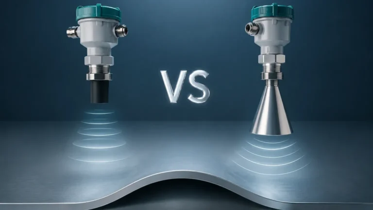
In the landscape of industrial automation, the term "ultrasonic t"—commonly referring to the ultrasonic transmitter or transducer system—represents one of the most versatile and cost-effective methods for non-contact level measurement. As industries move toward more automated and precise fluid management, understanding the technical nuances of an ultrasonic t setup is essential for engineers and plant managers. This guide provides a comprehensive technical overview of Ultrasonic Level Meters, their operating principles, selection criteria, and practical installation requirements.
1. Principles of Ultrasonic Level Measurement
Before selecting an ultrasonic t for a specific application, it is vital to understand the physics governing the technology. Ultrasonic level meters operate on the "Time-of-Flight" (ToF) principle.
The Transducer Mechanism
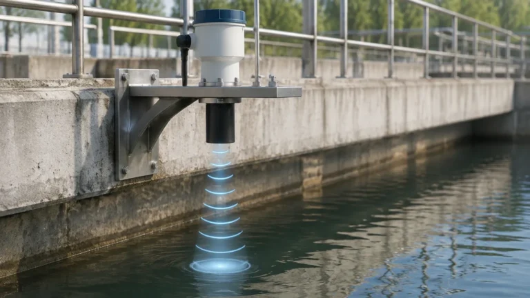
The core of the system is the transducer, which contains a piezoelectric crystal. When an electrical pulse is applied, the crystal vibrates, generating a burst of high-frequency sound waves. These waves travel through the air or gas medium in the tank, reflect off the surface of the material (liquid or solid), and return to the transducer. The transducer then acts as a receiver, converting the returning sound energy back into an electrical signal.
The Calculation Formula
The internal electronics of the ultrasonic t calculate the distance based on the time elapsed between the transmission and the reception of the pulse. The formula used is:
D = (c × t) / 2
Where:
* D is the distance from the sensor to the material surface.
* c is the speed of sound in the medium (approximately 343 m/s or 1,125 ft/s in air at 20°C).
* t is the total travel time (round trip).
Since the height of the tank (H) is known, the actual level (L) is determined by subtracting the distance (D) from the total height: L = H – D.
Temperature Compensation
The speed of sound is not constant; it varies with the temperature of the medium. For every 1°C change in temperature, the speed of sound changes by approximately 0.6 m/s (1.1 ft/s). To maintain accuracy, modern ultrasonic level meters include an integrated temperature sensor to provide real-time compensation for these variations.
2. Evaluating the Ultrasonic T: Key Components and Types
An ultrasonic t system generally consists of two main functional blocks: the sensor (transducer) and the transmitter (electronics). Depending on the application environment, these may be housed in a single unit or separated.
Integral vs. Remote Systems
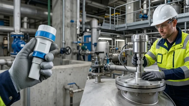
* Integral (Compact) Design: The transducer and the transmitter are housed in a single enclosure. This is the most common configuration for standard water treatment and chemical storage applications due to its ease of installation and lower cost.
* Remote (Split) Design: The transducer is installed at the measurement point, while the transmitter is mounted in a control room or a more accessible location. This is preferred in high-vibration environments or where the sensor must be mounted in hazardous areas while the display and controls remain in a safe zone.
Signal Processing and Echo Filtering
Advanced ultrasonic t units utilize digital signal processing (DSP) to distinguish the "true echo" from the surface of the material against "false echoes" caused by tank internal structures (ladders, agitators, or pipes). This is often referred to as "false echo suppression" or "mapping."
3. Practical Selection Criteria
Choosing the right ultrasonic t requires a detailed analysis of the process conditions. The following table provides a general reference for evaluating different ultrasonic level meter configurations based on typical industrial requirements.
Selection Reference Table
| Feature | Standard Liquid Application | Corrosive Chemical Storage | Solids/Powder Application |
| :— | :— | :— | :— |
| Measuring Range | 0.3m to 15m (1ft to 49ft) | 0.3m to 10m (1ft to 33ft) | 0.3m to 10m (1ft to 33ft) |
| Transducer Material | ABS / PVC | PVDF / PTFE | Reinforced Polymer |
| Beam Angle | 8° to 12° | 6° to 10° (Narrow preferred) | 10° to 15° |
| Accuracy | ±0.25% of range | ±0.25% of range | ±0.5% to 1% of range |
| Output Signal | 4-20mA, HART, RS485 | 4-20mA, HART | 4-20mA, Modbus |
| Pressure Limit | Atmospheric | Up to 0.3 MPa (43.5 psi) | Atmospheric |
Beam Angle and Frequency
The frequency of the ultrasonic t determines its range and beam angle. Higher frequencies (e.g., 60 kHz to 80 kHz) allow for smaller transducers and narrower beam angles, which are ideal for narrow tanks. Lower frequencies (e.g., 20 kHz to 40 kHz) are used for longer ranges and are better at penetrating dust or steam, though they require larger transducer faces.
4. Installation Considerations and Best Practices
The performance of an ultrasonic t is heavily dependent on correct physical installation. Even the most advanced sensor will fail if placed incorrectly.
The Dead Band (Blocking Distance)
Every ultrasonic t has a "dead band" or "blocking distance" directly beneath the transducer face (typically 0.2m to 0.5m / 8" to 20"). In this zone, the sensor cannot accurately measure because the crystal is still vibrating from the transmission pulse when the reflection returns. The sensor must be mounted high enough so that the maximum liquid level never enters this dead band.
Positioning and Alignment
* Avoid the Center: Do not mount the sensor in the exact center of a circular tank, as this can focus multiple reflections and create signal interference.
* Avoid the Wall: Stay away from the tank wall to prevent the beam from hitting the side and causing false echoes. A general rule is to keep the sensor at a distance from the wall equal to at least 1/6th of the tank height.
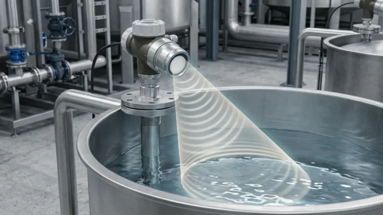
* Perpendicularity: The transducer face must be perfectly parallel to the liquid surface. A tilt of even a few degrees can cause the signal to bounce away from the sensor rather than back to it.
* Inlet Interference: Never install the ultrasonic t directly above the tank inlet. The turbulence and falling liquid will disrupt the signal and lead to erratic readings.
Mounting Nozzles
If the sensor is mounted on a nozzle, the nozzle must be as short and wide as possible. If the nozzle is too long or narrow, the ultrasonic pulse will reflect off the inside of the nozzle pipe before it even reaches the tank, resulting in a false high-level reading.

5. Limitations and Environmental Factors
While ultrasonic level meters are highly versatile, they are not suitable for every application. Engineers must be aware of the following limitations:
Foam and Turbulence
Heavy foam on the surface of a liquid acts as an acoustic absorber. Instead of reflecting the sound wave, the foam absorbs it, causing the ultrasonic t to lose the signal (a "Lost Echo" error). While light foam can sometimes be penetrated, thick, dense foam usually requires a different technology, such as a radar level meter or a hydrostatic transmitter.
Vacuum and High Pressure
Ultrasonic waves require a medium (gas/air) to travel. Therefore, an ultrasonic t cannot function in a vacuum. Furthermore, high-pressure environments change the density of the gas, which significantly alters the speed of sound and can exceed the compensation capabilities of standard instruments.
Dust and Vapor
Heavy dust in silos or dense steam/vapors in chemical tanks can scatter or attenuate the sound waves. In these environments, the signal strength decreases, reducing the effective measuring range. For applications with significant steam, ensure the sensor has a self-cleaning face or consider a higher-power transducer.
6. Maintenance and Troubleshooting
Ultrasonic level meters are generally low-maintenance because they have no moving parts and do not contact the process material. However, periodic checks are recommended.
* Transducer Cleaning: In applications where condensation or dust buildup occurs, the transducer face should be wiped periodically with a soft cloth. Do not use abrasive materials or solvents that could damage the polymer face.
* Diagnostic Checks: Most modern transmitters provide diagnostic values, such as "Signal Strength" or "Echo Quality." A sudden drop in signal strength often indicates buildup on the sensor or an increase in surface foam.
Frequently Asked Questions (FAQs)
Q: Can I use an ultrasonic t for measuring solids?
A: Yes, but with caution. Solids like grain, plastic pellets, or coal do not have a flat surface; they form cones. This scatters the signal. When measuring solids, you typically need a sensor with a higher power rating and a wider beam angle, and the effective range is usually reduced by 50% compared to liquids.
Q: What is the maximum temperature an ultrasonic t can handle?
A: Most standard ultrasonic transducers are rated for process temperatures between -40°C and +80°C (-40°F to 176°F). For higher temperatures, specialized sensors or different technologies like radar are required.
Q: How do I handle internal obstructions like agitators?
A: Most Ultrasonic Level Meters feature a "False Echo Mapping" function. You can program the unit to recognize the echo from the agitator as a fixed obstruction and ignore it, focusing only on the moving echo from the material surface.
Q: Is the ultrasonic t affected by the color or transparency of the liquid?
A: No. Unlike optical or laser sensors, ultrasonic technology relies on sound density. The color, transparency, or opacity of the liquid has no effect on the measurement accuracy.
Conclusion
The ultrasonic t is a cornerstone of modern level instrumentation, offering a reliable, non-contact solution for a wide range of industrial applications. By understanding the principles of sound propagation, respecting the limitations of the technology, and following strict installation guidelines, users can achieve high-precision level monitoring with minimal maintenance. For complex applications involving aggressive chemicals or challenging tank geometries, consulting with a technical specialist is recommended to ensure the selected configuration meets the specific demands of the process environment.