Ultrasonic Water Level Indicator Tinkercad
Ultrasonic Water Level Indicator Tinkercad: From Prototyping to Industrial Implementation
In the field of industrial automation and process control, accurate level measurement is a cornerstone of operational efficiency. For engineers and students alike, the journey often begins with simulation and prototyping. A common entry point is the development of an ultrasonic water level indicator tinkercad project, which allows for the virtual testing of logic and circuitry before deploying physical hardware. However, transitioning from a digital simulation to a robust industrial environment requires a deep understanding of the physics of sound, the limitations of hardware, and the specific requirements of professional-grade Ultrasonic Level Meters.
This guide explores the principles of ultrasonic measurement, compares hobbyist-level simulations with industrial realities, and provides a technical framework for selecting and installing level measurement solutions in demanding B2B applications.
The Principle of Ultrasonic Level Measurement
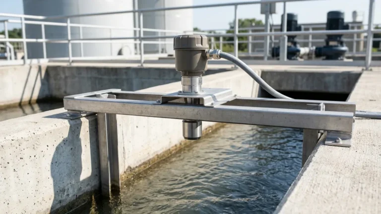
Ultrasonic measurement is a non-contact technology that utilizes high-frequency sound waves—typically above the range of human hearing (20 kHz to 200 kHz)—to determine the distance to a liquid or solid surface.
Time-of-Flight (ToF) Calculation
The core operating principle is the "Time-of-Flight" (ToF) method. An ultrasonic transducer acts as both a transmitter and a receiver. It emits a short burst of sound waves (an ultrasonic pulse) toward the target material. These waves travel through the air, reflect off the surface of the medium, and return to the transducer.
The distance ($D$) is calculated using the following formula:
$$D = \frac{c \times t}{2}$$
Where:
* $c$ is the speed of sound in the medium (approximately 343 m/s in air at 20°C).
* $t$ is the total time elapsed from the emission of the pulse to the reception of the echo.
Because the pulse travels to the surface and back, the result is divided by two to find the distance between the sensor and the material. In a tank application, the level of the liquid is then determined by subtracting this distance from the total height of the vessel.
Prototyping with Ultrasonic Water Level Indicator Tinkercad
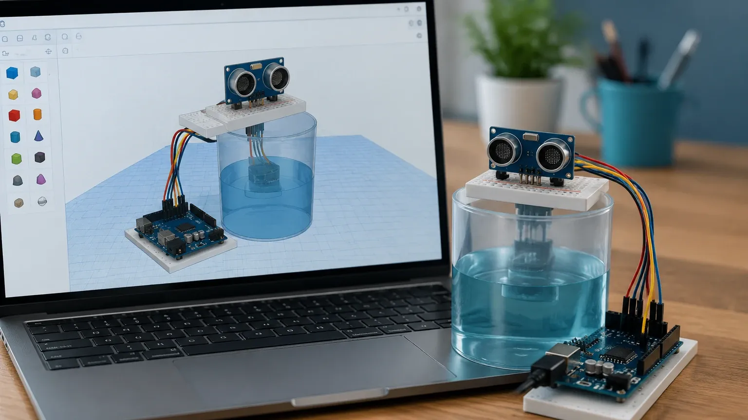
For those in the design or educational phase, using an ultrasonic water level indicator tinkercad simulation is an excellent way to validate the software logic. Tinkercad provides a virtual environment where users can wire an ultrasonic sensor (such as the HC-SR04) to a microcontroller (like an Arduino) and write code to process the distance data.
The Role of Simulation
* Logic Verification: Ensuring the code correctly converts time into distance and triggers alerts at specific thresholds.
* Circuit Design: Mapping out the wiring for power, ground, trigger, and echo pins without the risk of damaging physical components.
* Interface Testing: Simulating how data will be displayed on an LCD or sent to a serial monitor.
Transitioning to Industrial Reality
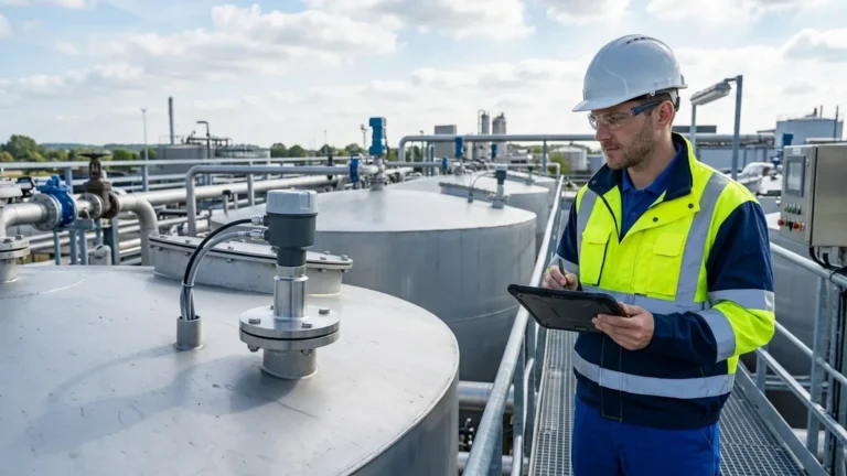
While Tinkercad is invaluable for conceptualizing a project, industrial applications demand far more than a basic HC-SR04 sensor can provide. Professional Ultrasonic Level Meters are engineered to withstand chemical exposure, high pressure, and extreme temperatures—factors that cannot be fully simulated in a basic digital environment. Industrial units feature specialized piezoelectric crystals, advanced digital signal processing (DSP), and ruggedized housings (IP66/67/68) to ensure long-term reliability.
Key Technical Specifications for Industrial Selection
When moving from a prototype to a functional industrial site, engineers must evaluate several critical parameters to ensure the chosen instrument meets the application's needs.
| Feature | Description | Industrial Standard |
| :— | :— | :— |
| Measurement Range | The minimum and maximum distance the sensor can accurately measure. | 0.3m to 30m (1 ft to 98 ft) |
| Beam Angle | The conical spread of the ultrasonic pulse. | 5° to 12° |
| Accuracy | The margin of error in the measurement. | ±0.2% to ±0.5% of full scale |
| Output Signal | How the data is transmitted to the control system (PLC/SCADA). | 4-20mA, RS485 (Modbus), HART |
| Temperature Compensation | Adjustment for the change in the speed of sound due to temperature fluctuations. | Integrated NTC/PT100 sensors |
| Blind Zone | The area directly in front of the transducer where measurement is impossible. | 0.2m to 0.5m (8 in to 20 in) |
Installation Guidelines and Best Practices
Proper installation is the most significant factor in the success of an ultrasonic level measurement system. Even the most advanced sensor will fail to provide accurate data if positioned incorrectly.
1. Avoiding the Blind Zone (Blocking Distance)
Every ultrasonic sensor has a "dead zone" or "blind zone" near the transducer face where it cannot receive an echo because the pulse is still being transmitted. Ensure the maximum liquid level never enters this zone. If necessary, use a standpipe or a taller mounting nozzle to lift the sensor higher above the maximum fill line.
2. Transducer Orientation
The transducer must be mounted perpendicular to the liquid surface. If the sensor is tilted, the ultrasonic pulse will reflect away from the receiver rather than back toward it, resulting in a "Loss of Echo" (LOE) error.
3. Obstacle Clearance and Beam Angle
Consider the beam angle when mounting the sensor near tank walls or internal structures. If the beam hits a ladder, agitator, or weld seam, it will create a false echo.
Calculation Tip: To calculate the radius ($R$) of the beam at a certain distance ($D$), use the formula:
$$R = D \times \tan(\frac{\text{Beam Angle}}{2})$$
Ensure that no obstructions fall within this radius throughout the entire measurement range.
4. Environmental Considerations
* Vapors and Gases: If the tank contains heavy vapors or gases other than air, the speed of sound will change, leading to measurement errors. In such cases, specialized calibration or radar level meters may be required.
* Turbulence and Foam: Heavy foam absorbs ultrasonic waves, while surface turbulence can scatter them. For turbulent liquids, a stilling well (a vertical pipe) can be used to provide a calm surface for measurement.
Limitations of Ultrasonic Technology
While highly versatile, ultrasonic sensors are not suitable for every application. Engineers should be aware of the following limitations:
* Vacuum Conditions: Sound waves require a medium (air/gas) to travel. Therefore, ultrasonic meters cannot function in a vacuum.
* High Pressure: High-pressure environments can alter the density of the air, significantly impacting the speed of sound and the transducer's ability to vibrate.
* Extreme Dust: In solid level measurement, excessive dust can attenuate the signal, though high-power transducers are often designed to overcome this.
* Temperature Gradients: Significant temperature differences between the liquid surface and the sensor can create "layers" in the air that refract the sound waves.
Frequently Asked Questions (FAQ)
Q: Can I use the code from my ultrasonic water level indicator tinkercad project for a professional PLC?
A: Not directly. Tinkercad usually involves C++ for Arduino. Industrial systems use PLC languages like Ladder Logic or Structured Text. However, the logic—calculating distance based on time—remains the same. Professional sensors usually output a 4-20mA signal, which the PLC scales to a level value.
Q: How does temperature affect the accuracy of my level meter?
A: The speed of sound increases by approximately 0.6 m/s for every degree Celsius increase in temperature. Without compensation, a 10°C change could result in a measurement error of nearly 2%. Industrial Welk sensors include built-in temperature probes to automatically correct this.
Q: What is the benefit of a 4-wire vs. 2-wire ultrasonic meter?
A: 2-wire meters are loop-powered, meaning they use the same two wires for both power and the 4-20mA signal, which simplifies wiring. 4-wire meters have separate power and signal lines, allowing for higher power consumption, which is often necessary for long-range measurements or sensors with integrated heaters for de-icing.
Q: Can ultrasonic sensors measure the level of solids like grain or sand?
A: Yes, but with considerations. Solids do not have a flat surface; they form a cone (angle of repose). This scatters the echo. For solids, it is recommended to use a sensor with a narrower beam angle and higher power to ensure a reliable return signal.
Conclusion
Starting with an ultrasonic water level indicator tinkercad model is a practical way to learn the fundamentals of non-contact level sensing. However, for industrial applications in water treatment, chemical processing, or oil and gas, the hardware must be capable of handling environmental stresses that a simulation cannot replicate. By selecting high-quality Ultrasonic Level Meters and following rigorous installation standards, facilities can achieve precise, maintenance-free level monitoring that ensures both safety and productivity.
Download Ultrasonic Water Level Indicator Tinkercad as a PDF