4 Ultrasonic Flow Meter
4 Ultrasonic Flow Meter: A Technical Guide to Selection and Application
In industrial process control, the precise measurement of liquid movement and storage is fundamental to operational efficiency. Among the various technologies available, ultrasonic measurement stands out for its non-invasive nature and reliability. While often discussed in the context of Ultrasonic Level Meters, the technology is equally critical for flow measurement. This guide explores the specifics of the 4 ultrasonic flow meter—referring both to 4-inch (DN100) pipe applications and advanced 4-path measurement systems—and how these technologies integrate with broader level and flow management strategies.
Understanding Ultrasonic Measurement Principles
Before selecting a 4 ultrasonic flow meter, it is essential to understand the physics governing the measurement. Ultrasonic instruments utilize sound waves at frequencies above the range of human hearing (typically 20 kHz to several MHz). There are two primary methods used in flow measurement: Transit-Time and Doppler Effect.
Transit-Time Principle
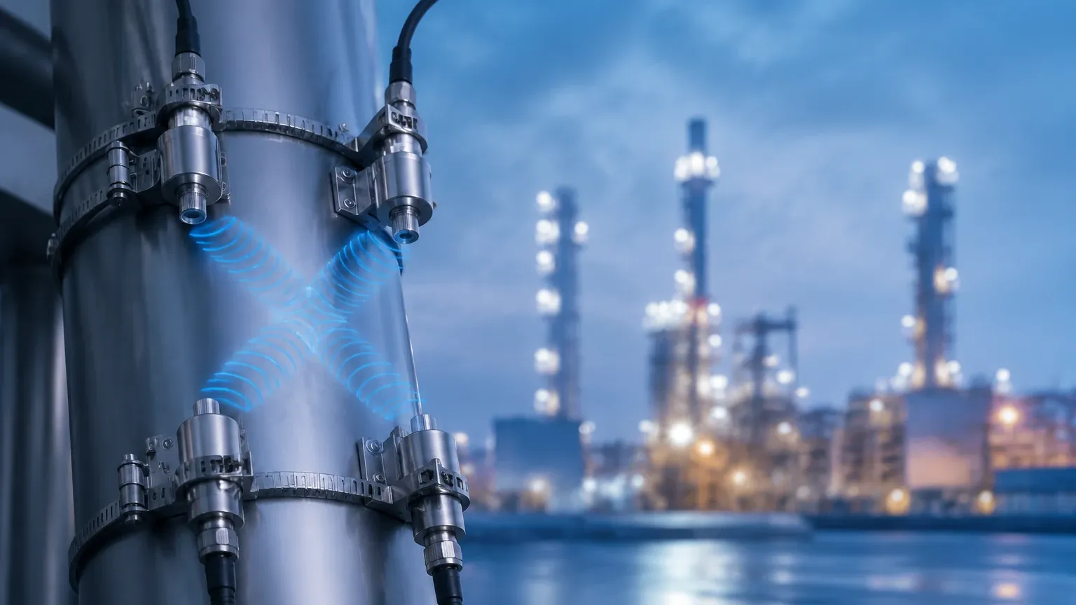
Transit-time ultrasonic flow meters operate by transmitting and receiving ultrasonic pulses between two transducers. One pulse is sent in the direction of the flow (downstream), and another is sent against the flow (upstream).
* Downstream travel time ($t_1$): The sound wave is accelerated by the fluid velocity.
* Upstream travel time ($t_2$): The sound wave is slowed by the fluid velocity.
The difference in these travel times ($Δt$) is directly proportional to the velocity of the liquid. For a 4-inch (100 mm) pipe, this method is highly effective for clean liquids like water, chemicals, and light oils.
Doppler Effect Principle
Doppler flow meters function by reflecting sound waves off particles or bubbles (discontinuities) within the flowing liquid. The frequency shift between the transmitted and received signal is used to calculate the flow velocity. This method is preferred for slurries, wastewater, or aerated liquids where transit-time signals would be scattered or absorbed.
The Role of "4-Path" Technology
In the context of high-precision measurement, a "4 ultrasonic flow meter" often refers to a multi-path meter. By using four pairs of transducers (four paths), the meter can sample the flow velocity at different points across the pipe's cross-section. This compensates for non-ideal flow profiles (turbulence or swirl) and significantly increases accuracy compared to single-path meters, which are more sensitive to flow disturbances.
The Intersection of Level and Flow: Open Channel Applications
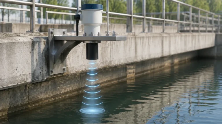
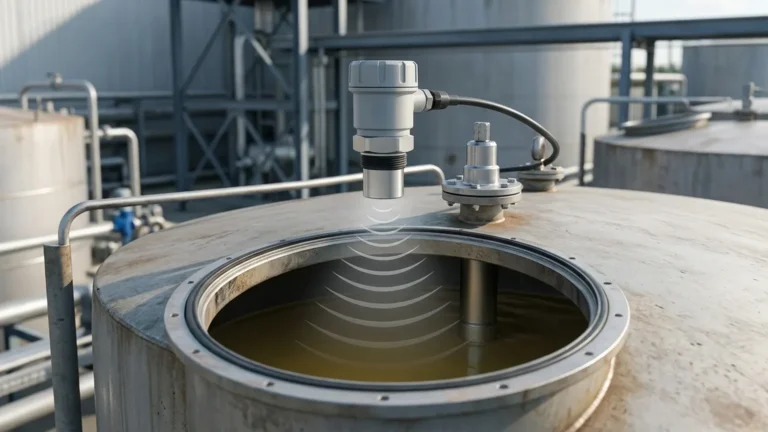
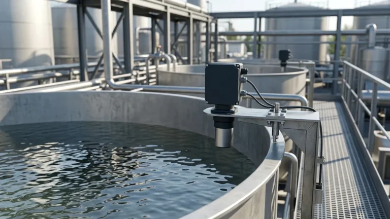
It is important to note that many industrial facilities use Ultrasonic Level Meters to calculate flow in open channels. In these scenarios, the level meter measures the head (height) of the liquid behind a primary device, such as a weir or flume. Using programmed hydraulic equations (e.g., Manning’s equation), the instrument converts the level reading into a flow rate. This is a common application for a 4-inch flume setup in water treatment plants.
Key Evaluation Criteria for a 4 Ultrasonic Flow Meter
When specifying a 4-inch (DN100) ultrasonic flow meter or a 4-path system, engineers must evaluate several technical parameters to ensure long-term performance.
1. Fluid Characteristics
The nature of the fluid is the primary determinant of sensor type.
* Clean Liquids: Transit-time meters are ideal.
* Suspended Solids (>100 ppm): Doppler meters or hybrid systems are required.
* Viscosity: High-viscosity fluids can affect the flow profile, necessitating multi-path (4-path) correction.
2. Pipe Material and Condition
For clamp-on ultrasonic flow meters, the sound wave must pass through the pipe wall.
* Materials: Carbon steel, stainless steel, PVC, and ductile iron are generally compatible.
* Liners: Cement or rubber liners can attenuate the signal. If a 4-inch pipe is lined, the thickness of the liner must be accounted for in the meter's configuration.
* Scaling: Internal scale buildup in older 4-inch pipes can create air gaps that block ultrasonic signals.
3. Accuracy Requirements
* Single-path meters: Typically offer 1.0% to 2.0% accuracy.
* 4-path meters: Can achieve accuracies of 0.5% or better, making them suitable for custody transfer or high-value chemical dosing.
4. Output and Integration
Modern industrial environments require seamless integration with PLC or SCADA systems. Most 4 ultrasonic flow meters provide:
* Analog: 4-20mA current loops.
* Digital: Modbus RTU, HART, or Profibus.
* Pulse: For totalizing flow volume.
Selection Table: Ultrasonic Flow Meter vs. Level Meter for Flow
| Feature | Inline 4-Path Flow Meter | Clamp-on 4" Flow Meter | Ultrasonic Level (Open Channel) |
| :— | :— | :— | :— |
| Application | High-precision process control | Temporary measurement/Retrofit | Wastewater flumes/weirs |
| Installation | Requires pipe cutting | Non-invasive (no downtime) | Above the liquid surface |
| Fluid Type | Clean to slightly dirty | Clean liquids | Any (non-contact) |
| Pipe Size | Fixed (e.g., DN100) | Versatile (e.g., 25mm to 1000mm) | N/A (Open channel) |
| Maintenance | Low | Very Low | Minimal (no moving parts) |
Installation Considerations for 4-Inch Systems
To achieve the specified accuracy of a 4 ultrasonic flow meter, proper installation is non-negotiable. Poor placement is the leading cause of measurement error in ultrasonic systems.
Straight Pipe Run Requirements
Ultrasonic meters require a fully developed flow profile. For a standard 4-inch (DN100) pipe, the general rule is:
* Upstream: 10 diameters (10D = 1000 mm) of straight pipe after elbows or valves.
* Downstream: 5 diameters (5D = 500 mm) of straight pipe before the next fitting.
If a 4-path meter is used, these requirements may be slightly reduced due to the meter's ability to compensate for turbulence, but adhering to the 10D/5D rule remains best practice.
Transducer Mounting (Clamp-on)
For 4-inch pipes, transducers are typically mounted in one of two configurations:
* V-Method: The signal bounces off the opposite pipe wall once. This is the standard for 4-inch (DN100) pipes as it provides a longer path length and better resolution.
* Z-Method: The signal passes directly across the pipe. This is usually reserved for larger pipes or highly attenuative liquids where the signal strength is a concern.
Acoustic Coupling
For clamp-on 4 ultrasonic flow meters, an acoustic coupling grease or pad must be used between the transducer face and the pipe wall. This eliminates air gaps that would otherwise reflect the ultrasonic energy back into the sensor.
Limitations and Common Risks
While ultrasonic technology is robust, it is not universal. Engineers should be aware of the following limitations:
1. Entrained Air: Large bubbles in the liquid reflect ultrasonic signals. If a 4-inch pipe is only partially full, a transit-time flow meter will fail. In such cases, switching to an Ultrasonic Level Meters approach in an open-channel configuration is more reliable.
2. Temperature Extremes: High temperatures can affect the speed of sound in the liquid and the pipe material. Sensors must be rated for the process temperature, and the meter's software must include temperature compensation.
3. Acoustic Short-Circuiting: In some metal pipes, the ultrasonic signal can travel through the pipe wall faster than through the liquid. High-quality 4-path meters use signal processing to filter out these "wall-borne" signals.
Practical Maintenance Guidance
Ultrasonic instruments are favored for their low maintenance requirements, as they lack moving parts that wear out. However, periodic checks are necessary:
* Signal Strength: Monitor the gain or signal-to-noise ratio (SNR) on the meter display. A significant drop may indicate coupling grease degradation or internal pipe scaling.
* Transducer Alignment: In high-vibration environments, clamp-on transducers may shift. Ensure they remain securely fastened at the calculated distance.
* Calibration: While the electronics rarely drift, the physical parameters (pipe wall thickness, liquid temperature) can change. Annual verification against a master meter is recommended for critical 4-path applications.
Frequently Asked Questions (FAQ)
Q: Can a 4 ultrasonic flow meter measure gas?
A: Most standard industrial ultrasonic meters are designed for liquids. Gas flow measurement requires specific high-frequency transducers and different signal processing due to the much lower density of gas compared to liquid.
Q: How does a 4-path meter differ from a 2-path meter?
A: A 2-path meter uses two acoustic beams, typically in a cross-pattern. A 4-path meter adds two additional beams, providing a more comprehensive map of the flow velocity distribution. This makes the 4-path version significantly more accurate in turbulent conditions.
Q: Is it better to use a clamp-on or an inline 4-inch meter?
A: Clamp-on meters are ideal for retrofitting existing systems without stopping production. Inline meters (where the transducers are pre-installed in a pipe section) are generally more accurate because the path length and pipe geometry are factory-calibrated.
Q: How do I measure flow if my 4-inch pipe is not always full?
A: Ultrasonic transit-time meters cannot measure partially full pipes. You should either move the meter to a section of the pipe that is always full (e.g., a U-bend) or use an area-velocity flow meter that combines ultrasonic level measurement with Doppler velocity sensing.
Conclusion
Selecting a 4 ultrasonic flow meter requires a balance between accuracy requirements, fluid characteristics, and installation constraints. Whether utilizing a 4-path high-precision system or a 4-inch clamp-on unit for general monitoring, understanding the underlying acoustic principles is key to success. For applications involving open channels or tank inventories, integrating Ultrasonic Level Meters provides a versatile solution that complements inline flow measurement. By following rigorous installation standards and selecting the appropriate measurement path configuration, industrial operators can ensure reliable data for process optimization and resource management.