Ultrasonic Level Sensor Diy
Ultrasonic Level Sensor DIY: From Prototyping to Industrial Implementation
In the realm of process automation and liquid management, level measurement is a fundamental requirement. For engineers, hobbyists, and system integrators, the concept of an ultrasonic level sensor diy project often serves as the first step toward understanding non-contact measurement technology. While DIY solutions provide an excellent educational foundation and work well for low-stakes applications like domestic water tank monitoring, industrial environments demand a higher level of precision, durability, and integration.
This guide explores the principles of ultrasonic measurement, the components required for a DIY setup, and the critical transition points where a professional industrial solution becomes necessary.
Understanding the Measurement Principle
Before embarking on an ultrasonic level sensor diy build, it is essential to understand the physics governing the technology. Ultrasonic level meters operate on the "Time of Flight" (ToF) principle.
The Time of Flight (ToF) Calculation
The sensor's transducer emits a high-frequency sound pulse (usually between 20 kHz and 200 kHz). This pulse travels through the air, hits the surface of the medium (liquid or solid), and reflects back to the sensor. The device measures the time interval between the emission of the pulse and the reception of the echo.
Using the known speed of sound in air, the distance is calculated using the following formula:
Distance = (Speed of Sound × Time) / 2
The result is divided by two because the sound wave travels to the surface and back. To determine the actual liquid level, the measured distance is subtracted from the total height of the tank (the distance from the sensor face to the tank bottom).
Environmental Variables
A critical factor often overlooked in basic DIY projects is that the speed of sound is not constant; it varies with temperature. At 0°C, sound travels at approximately 331.5 m/s, whereas at 20°C, it travels at 343.4 m/s. Without temperature compensation, a DIY sensor can experience significant accuracy drift as the ambient environment changes.
Components of an Ultrasonic Level Sensor DIY Project
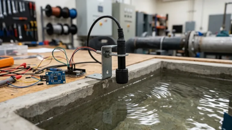
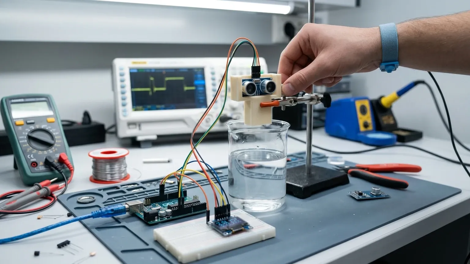
Building a functional prototype typically involves four core components. For those looking to experiment, these parts are readily available and cost-effective:
1. The Ultrasonic Module: The most common DIY module is the HC-SR04, which is suitable for indoor, clean-water applications. For outdoor or more rugged use, the JSN-SR04T is often preferred because it features a waterproof probe.
2. Microcontroller: An Arduino (Uno or Nano) or an ESP32 is standard. The ESP32 is particularly popular for modern DIY projects because it includes built-in Wi-Fi and Bluetooth for remote monitoring.
3. Power Supply: Most modules require a stable 5V DC input. In industrial settings, this is usually stepped down from a 24V DC rail.
4. Display/Output: A simple 16×2 LCD or an OLED display provides local readings, while the serial monitor on a PC handles debugging.
Basic Wiring and Logic
In a typical ultrasonic level sensor diy setup, the microcontroller triggers the sensor by sending a 10-microsecond pulse to the "Trig" pin. The sensor then emits eight ultrasonic bursts. The "Echo" pin goes high until the reflection is received. The microcontroller measures the duration of this high signal to calculate the distance.
Selection Criteria: DIY vs. Industrial Grade
When evaluating whether to build a custom solution or purchase professional Ultrasonic Level Meters, engineers must consider the application's risk profile and environmental conditions.
| Feature | DIY Prototype (e.g., HC-SR04/Arduino) | Industrial Ultrasonic Level Meter |
| :— | :— | :— |
| Measurement Range | 0.02m to 4m | 0.3m to 30m+ |
| Accuracy | ±3mm to ±10mm (uncompensated) | ±0.25% of range (compensated) |
| Output Signal | TTL Serial / PWM | 4-20mA, Modbus RTU, HART |
| Ingress Protection | None or IP65 (probe only) | IP66, IP67, or IP68 (Full unit) |
| Temp. Compensation | Manual/Software-based | Integrated Automatic Compensation |
| Signal Processing | Basic thresholding | False echo suppression / Agitator filtering |
| Mounting | Custom brackets | Standard Threaded (G/NPT) or Flanged |
Practical Installation Considerations
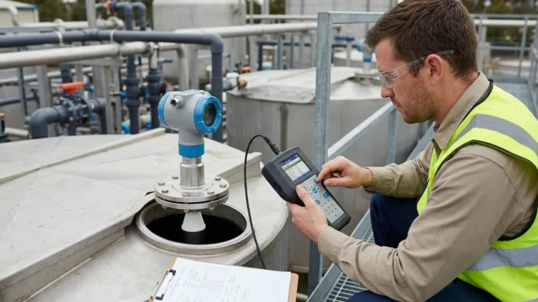
Whether using a DIY kit or a professional instrument, the physical installation determines the reliability of the data. Improper mounting is the leading cause of measurement failure in ultrasonic systems.
1. The Dead Zone (Blind Zone)
Every ultrasonic sensor has a "dead zone" immediately in front of the transducer face where it cannot measure. This is caused by the transducer's need to stop vibrating after emitting a pulse before it can listen for the return.
* DIY Impact: Cheap sensors often have a 20cm to 25cm dead zone. If the liquid rises into this area, the reading will be erratic or fixed at the minimum distance.
* Solution: Mount the sensor high enough above the maximum possible liquid level to ensure the surface never enters the dead zone.
2. Beam Angle and Obstructions
The ultrasonic pulse does not travel in a straight line; it spreads out in a cone (typically 5° to 15°). If this cone hits a tank wall, a ladder, or a pipe before hitting the liquid, the sensor will report the distance to that obstruction.
* Guideline: Ensure a clear path for the beam. The distance from the sensor center to the tank wall should be at least 1/10th of the total tank height.
3. Surface Conditions
Ultrasonic waves require a solid or liquid surface to reflect.
* Foam: Heavy foam absorbs sound waves, often resulting in a "Loss of Echo" (LOE) error.
* Turbulence: Rapidly moving or boiling liquids can scatter the signal. In these cases, a stilling well (a vertical pipe) can be used to provide a calm surface for measurement.
Limitations and Common Risks
While an ultrasonic level sensor diy project is a powerful learning tool, it faces several limitations in professional process environments:
* Pressure Variations: Ultrasonic sensors are generally designed for atmospheric pressure. Significant vacuum or high-pressure conditions change the density of the air, which drastically alters the speed of sound and can even prevent the transducer from vibrating correctly.
* Chemical Compatibility: DIY sensors often use aluminum or exposed piezoelectric elements. Industrial meters utilize PVDF, PTFE, or PP housings to resist corrosion from acids and bases.
* Signal Noise: Industrial plants are electrically "noisy" environments. A DIY microcontroller without proper shielding and optoisolation is prone to crashes or false readings due to electromagnetic interference (EMI) from motors and VFDs.
Moving from Prototype to Professional Solutions
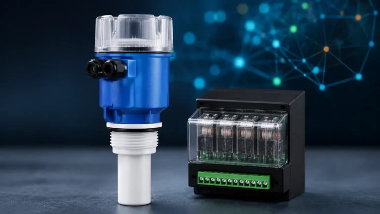
For many organizations, the DIY phase is used to prove the concept. Once the logic is verified, the transition to a factory-calibrated unit like those found in the Welk catalog is necessary for long-term reliability. Professional Ultrasonic Level Meters integrate advanced algorithms that can filter out "false echoes" caused by internal tank structures—a feature nearly impossible to replicate reliably in a standard DIY script.
Furthermore, industrial units provide standard 4-20mA loop-powered outputs, allowing them to interface directly with PLC (Programmable Logic Controller) and SCADA systems without the need for custom intermediate code.
Frequently Asked Questions (FAQ)
Q: Can I use a DIY ultrasonic sensor for fuel or oil level?
A: It is not recommended. Many DIY sensors are not intrinsically safe or explosion-proof. Fuel vapors can be ignited by non-rated electronics, and the vapors themselves can affect the speed of sound differently than air. For these applications, specialized industrial sensors are required.
Q: How do I handle condensation on the sensor face?
A: Condensation can attenuate the signal. Industrial sensors often have a curved face or a vibrating self-cleaning cycle to shed droplets. In a DIY setup, you may need to mount the sensor at a slight angle or use a protective thin film, though this complicates calibration.
Q: What is the maximum distance a DIY sensor can measure?
A: Most low-cost DIY modules are limited to 4 or 5 meters. Beyond this, the signal strength weakens significantly, and the signal-to-noise ratio becomes too poor for reliable measurement without professional-grade amplification and processing.
Q: Is it possible to calibrate a DIY sensor for different temperatures?
A: Yes, by adding a DS18B20 temperature sensor to your microcontroller, you can update the speed of sound variable in your code in real-time. However, this only accounts for the temperature at the sensor, not necessarily the temperature gradient throughout the entire tank height.
Conclusion
An ultrasonic level sensor diy approach is an excellent way to explore the mechanics of non-contact level measurement and is perfectly suitable for simple, non-critical tasks. However, when the application involves chemical storage, high-value liquids, or integration into a factory automation network, the limitations of DIY components become apparent. In these scenarios, investing in professional-grade instrumentation ensures the accuracy, safety, and longevity required for industrial operations.