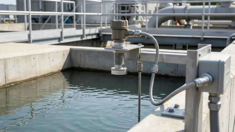
Ultrasonic Level Indicators
Ultrasonic Level Indicators: A Technical Guide to Non-Contact Measurement
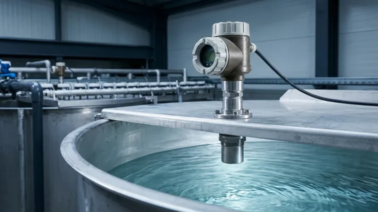
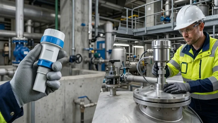
In modern industrial automation, the ability to monitor liquid and solid levels accurately without physical contact is a significant advantage. Ultrasonic level indicators, often categorized under the broader umbrella of Ultrasonic Level Meters, have become a standard solution for diverse sectors including water treatment, chemical processing, and food production.
By leveraging high-frequency sound waves, these instruments provide a reliable, maintenance-free method of monitoring inventory and controlling processes. This guide provides a comprehensive overview of the principles, selection criteria, and installation best practices for engineering professionals looking to integrate ultrasonic technology into their operations.
1. Measurement Principles of Ultrasonic Technology
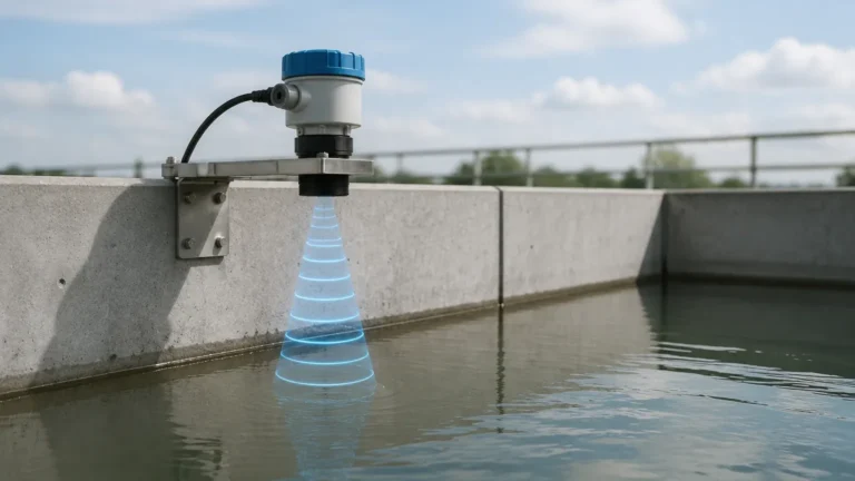
To understand how ultrasonic level indicators function, one must look at the physics of sound propagation. At its core, the device utilizes the "Time-of-Flight" (ToF) principle.
The Transducer and Pulse Emission
The heart of the instrument is the ultrasonic transducer, which usually contains a piezoelectric crystal. When an electrical pulse is applied, the crystal vibrates at a specific frequency, emitting a burst of ultrasonic sound waves (typically ranging from 20 kHz to 70 kHz). These waves travel through the air or gas space in a vessel until they encounter the surface of the material being measured.
Reflection and Detection
Upon hitting the surface—whether it is a liquid, slurry, or solid—a portion of the sound energy is reflected back toward the sensor as an echo. The transducer then acts as a microphone, converting the returning mechanical energy back into an electrical signal.
Distance Calculation
The internal microprocessor measures the time interval ($t$) between the emission of the pulse and the reception of the echo. Given that the speed of sound ($c$) in air is approximately 344 m/s (at 20°C), the distance ($D$) from the sensor to the surface is calculated using the formula:
$$D = \frac{c \times t}{2}$$
Since the total height of the tank ($H$) is a known programmed value, the level of the material ($L$) is determined by subtracting the measured distance from the total height: $L = H – D$.
Temperature Compensation
The speed of sound is highly dependent on the temperature of the medium through which it travels. For every 1°C change in temperature, the speed of sound changes by approximately 0.17%. To maintain accuracy, modern ultrasonic level indicators from manufacturers like Welk include integrated temperature sensors to automatically compensate for these fluctuations in real-time.
2. Types of Ultrasonic Level Indicators
Depending on the application requirements, ultrasonic instruments are designed in several configurations. Choosing the right architecture is critical for both performance and ease of maintenance.
Integrated (Compact) Design
In an integrated unit, the transducer and the electronics/display are housed in a single enclosure. This is the most common configuration for standard industrial tanks. It simplifies wiring, as only a single power/signal cable is required. Integrated units are ideal for outdoor sumps, water tanks, and chemical storage where space is not a primary constraint.
Remote (Split) Design
A remote system separates the transducer from the control unit (the indicator). The transducer is mounted at the measurement point, while the display and control interface are installed at eye level or in a control room, sometimes hundreds of meters away. This is preferred in hazardous environments, high-vibration areas, or when the measurement point is difficult to access for routine monitoring.
Power and Output Configurations
* 2-Wire (Loop Powered): The device is powered by the 4-20mA signal loop. These are energy-efficient and simpler to install but may have limitations in signal processing power for very complex applications.
* 4-Wire: These units have separate power supply and signal output wires. They generally offer stronger pulse emission and more advanced signal processing, making them suitable for longer ranges or more challenging environments.
3. Practical Selection Criteria
Selecting the appropriate ultrasonic level indicators requires an evaluation of the process environment and the physical properties of the medium. The following table provides a general comparison of common specifications found in Welk’s product line.
Table 1: Technical Selection Matrix
| Feature | Standard Liquid Application | Solids/Granular Application | Corrosive Chemical Application |
| :— | :— | :— | :— |
| Measuring Range | 0.4m to 15m (up to 30m) | 0.4m to 10m | 0.4m to 12m |
| Accuracy | ±0.25% to ±0.5% FS | ±0.5% to ±1% FS | ±0.25% FS |
| Transducer Material | ABS / PVC | Reinforced Nylon | PVDF / PTFE |
| Beam Angle | 6° to 12° | 8° to 15° | 6° to 10° |
| Output Signal | 4-20mA, RS485 | 4-20mA, Modbus | 4-20mA, HART |
| Process Temp. | -20°C to +60°C | -20°C to +60°C | -40°C to +80°C |
| Protection Class | IP66 / IP67 | IP65 | IP68 |
Key Considerations for Selection:
1. Measuring Range: Always select a meter with a range that exceeds the maximum depth of your tank by at least 10-20% to ensure reliability at the bottom of the vessel.
2. Chemical Compatibility: For acidic or alkaline liquids, the transducer face must be coated with or made of chemically resistant materials like PVDF.
3. Beam Angle: A narrower beam angle is better for narrow tanks or tanks with internal obstructions (ladders, pipes), as it reduces the risk of false echoes.
4. Installation Best Practices
The performance of ultrasonic level indicators is often determined by the quality of the installation. Even the most advanced sensor will fail if it is positioned incorrectly.
The Blocking Distance (Dead Zone)
Every ultrasonic sensor has a "dead zone" directly beneath the transducer face where it cannot measure. This is the time required for the transducer to stop vibrating after emitting a pulse before it can listen for the echo. Typically, this is between 0.2m and 0.5m. The sensor must be mounted high enough so that the maximum liquid level never enters this zone.
Mounting Location and Orientation
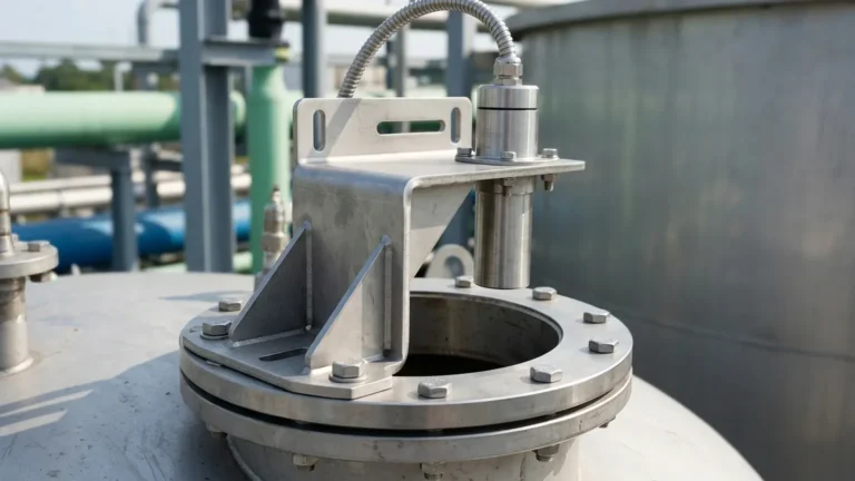
* Perpendicularity: The transducer must be mounted perfectly perpendicular to the liquid surface. A tilt of even a few degrees can cause the reflected signal to miss the sensor, resulting in a "Loss of Echo" error.
* Wall Distance: To avoid interference from wall reflections, the sensor should be mounted at a distance from the tank wall equal to at least 1/6th of the tank height.
* Fill Stream Avoidance: Never mount the sensor directly above the fill inlet. The falling liquid or dust will interfere with the ultrasonic pulse and create erratic readings.
Obstructions
Internal structures like heating coils, agitators, or ladders can create false echoes. If these cannot be avoided, many Welk ultrasonic level meters feature "False Echo Suppression" software, allowing the user to program the device to ignore reflections from fixed internal objects.

5. Limitations and Common Risks
While ultrasonic level indicators are versatile, they are not universal solutions. Understanding their limitations prevents costly misapplications.
Surface Conditions (Foam and Turbulence)
Heavy foam on a liquid surface acts as an acoustic insulator, absorbing the ultrasonic pulse rather than reflecting it. In such cases, the signal may be lost entirely. Similarly, extreme turbulence can scatter the sound waves. For these applications, a stilling well or a different technology, like radar or hydrostatic pressure sensors, may be required.
Atmospheric Interference
* Vapor and Steam: High concentrations of heavy vapors or steam can change the density of the air, affecting the speed of sound and causing measurement errors.
* Dust: In solid applications, heavy dust during the filling process can attenuate the signal.
* Pressure: Ultrasonic meters are generally designed for atmospheric pressure. High-pressure environments (typically above 0.3 MPa) change the medium's density significantly, which can impede sound wave propagation.
Temperature Extremes
Because the speed of sound is so sensitive to temperature, applications with rapid temperature gradients (e.g., a cold tank being filled with hot liquid) can lead to temporary inaccuracies until the internal compensation sensor stabilizes.
6. Maintenance and Troubleshooting
One of the primary benefits of non-contact ultrasonic level indicators is the lack of moving parts, which minimizes wear and tear. However, periodic checks are recommended.
* Transducer Cleaning: In applications with high humidity or splashing, condensation or material buildup can occur on the transducer face. This should be wiped clean with a soft cloth and mild detergent. Do not use abrasive materials that could scratch the transducer surface.
* Signal Strength Monitoring: Most digital indicators provide a signal strength or "Echo Quality" metric. A gradual decline in this value often indicates buildup on the sensor or a change in the process environment (e.g., increasing foam).
* Cable Integrity: Ensure that cable glands are tight and that there is no moisture ingress into the terminal housing, as this is the most common cause of electronic failure in outdoor installations.
7. Frequently Asked Questions (FAQ)
Q: Can ultrasonic level indicators measure the level of solids?
A: Yes, but with caveats. Solids like grain, pellets, or powders reflect sound differently than liquids. They often create a conical shape when piled, which can scatter the sound. A higher-power sensor with a wider beam and specific signal processing for solids is usually required.
Q: How does wind affect outdoor ultrasonic measurements?
A: Strong winds can "blow" the sound waves away or create air turbulence that dissipates the signal. For outdoor sumps or open channels, using a protective shroud or a sensor with a higher acoustic power output can mitigate this.
Q: What is the difference between an ultrasonic level indicator and a radar level meter?
A: Ultrasonic meters use sound waves and require a medium (air) to travel through. Radar meters use electromagnetic waves and can operate in a vacuum. Radar is generally better for high-temperature, high-pressure, or heavy-foam applications but is typically more expensive than ultrasonic solutions.
Q: Is it possible to use ultrasonic sensors in a vacuum?
A: No. Sound waves require a medium (gas or liquid) to propagate. In a vacuum, there is no air to carry the sound pulse, making ultrasonic measurement impossible.
Conclusion
Ultrasonic level indicators represent a cost-effective, reliable, and easy-to-install solution for a vast majority of industrial level monitoring needs. By understanding the acoustic principles and adhering to strict installation guidelines, engineers can ensure long-term accuracy and process safety. For applications requiring high precision and robust performance, Welk provides a range of Ultrasonic Level Meters designed to meet the rigors of modern industrial environments.
When selecting a system, always confirm the process temperature, pressure, and the presence of any potential acoustic absorbers like foam to ensure the technology is the right fit for your specific project requirements.