Float Level Switches
Float Level Switches
In the landscape of industrial automation and process control, the requirement for reliable point-level detection remains a cornerstone of safety and efficiency. Float level switches represent one of the most established and cost-effective technologies for managing liquid levels in tanks, sumps, and vessels. As a primary category within the broader family of Level Switches, these devices utilize the fundamental principles of buoyancy to provide discrete output signals, typically used for high-level alarms, low-level protection, or automated pump control.
For engineers and facility managers, understanding the nuances of float switch design—ranging from magnetic reed switch mechanisms to heavy-duty mechanical linkages—is essential for ensuring long-term operational stability. This guide provides a technical overview of float level switch principles, selection criteria, and practical installation strategies for industrial environments.
Measurement Principles of Float Level Switches
The operation of a float level switch is governed by Archimedes' principle, which states that any object, wholly or partially immersed in a fluid, is buoyed up by a force equal to the weight of the fluid displaced by the object. In practical application, the "float" is designed with a lower density than the process liquid, allowing it to move vertically or pivot as the liquid level changes.
There are two primary internal mechanisms used to convert this physical movement into an electrical signal:
1. Magnetic Reed Switch Mechanism
This is the most common design for modern industrial applications. The float contains an internal permanent magnet. As the liquid level rises or falls, the float slides along a stationary stem. Inside the hermetically sealed stem, one or more reed switches are positioned at specific set points. When the float's magnetic field aligns with the reed switch, the contact closes (or opens), triggering the electrical circuit. Because the electrical components are isolated from the process media within the stem, this design offers high reliability and resistance to corrosion.
2. Mechanical Microswitch Mechanism
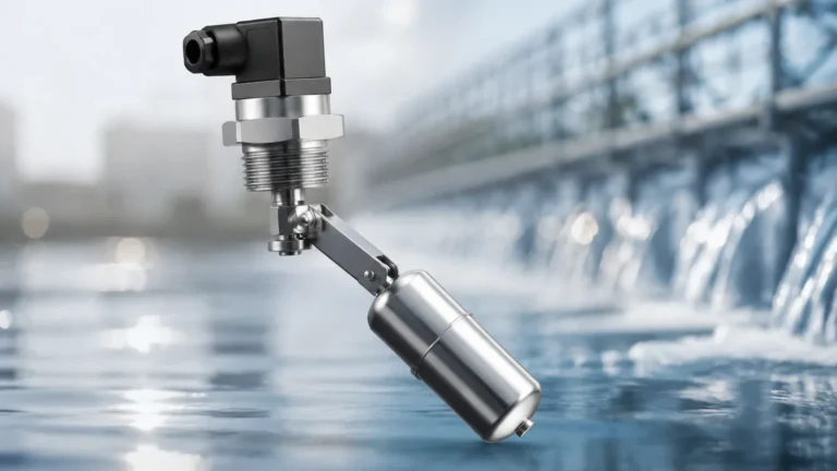
Commonly found in side-mounted or large-scale cable-suspended switches, this design uses the physical force of the float's movement to actuate a microswitch. In a side-mounted horizontal float switch, the float is attached to a pivot arm. As the float rises, the arm moves a linkage—often through a bellows or a magnetic coupling—to trigger a snap-action switch located in the external housing. This design is robust and often preferred for high-power switching applications where a reed switch might be insufficient.
Types of Float Level Switches
Selecting the correct configuration depends heavily on the tank geometry and the specific requirements of the process. The following are the standard industrial types:
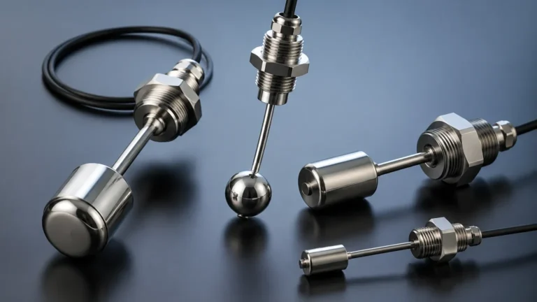
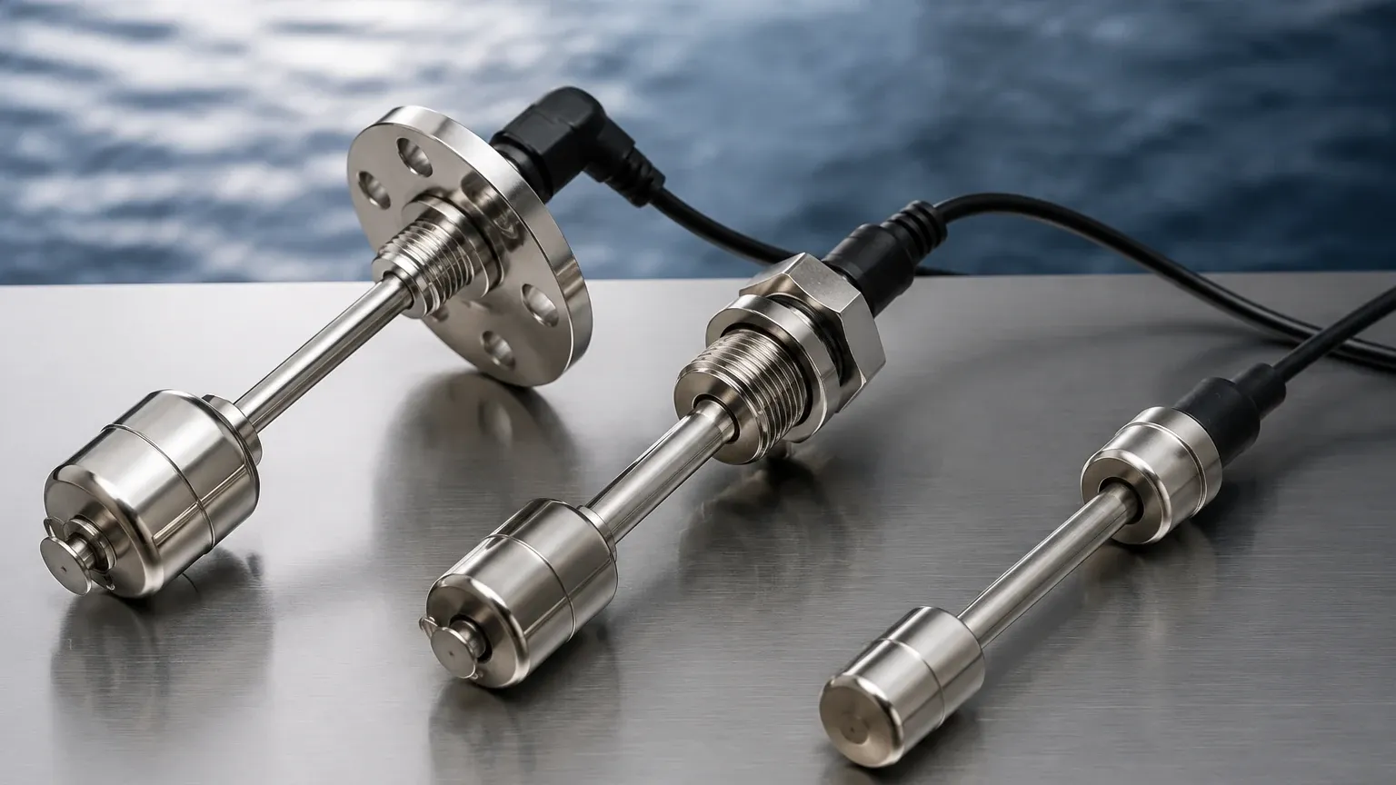
* Vertical Stem Float Switches: These are mounted at the top or bottom of a tank. A single stem can house multiple reed switches, allowing for multi-point detection (e.g., Low-Low, Low, High, and High-High) with a single process entry.
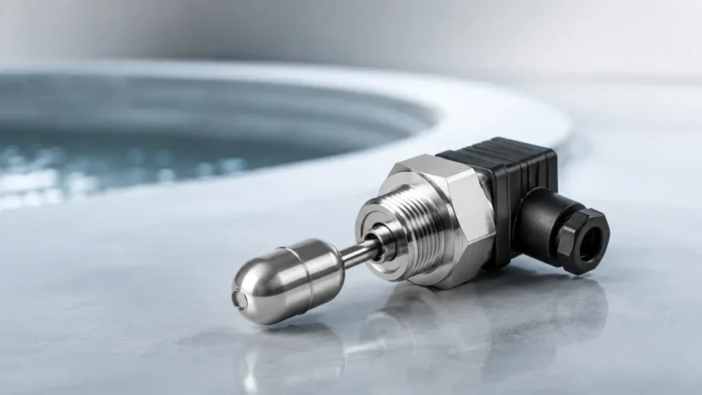
* Side-Mounted (Horizontal) Float Switches: Installed through the side wall of a vessel, these are ideal for tanks where top access is restricted. They typically provide a single set point.
* Cable-Suspended Float Switches: Often used in wastewater and large sumps, these consist of a weighted float suspended by a flexible cable. The switch triggers when the float tilts beyond a certain angle. They are highly tolerant of turbulent surfaces and debris.
* Miniature Float Switches: Designed for OEM equipment and small tanks, these use compact plastic or stainless steel floats for space-constrained applications.
Key Evaluation and Selection Criteria
To ensure a float level switch performs reliably, several technical parameters must be confirmed during the specification phase. Failure to match the switch to the process conditions often leads to premature mechanical failure or inaccurate switching.
Specific Gravity (Density)
The most critical factor is the specific gravity (S.G.) of the liquid. The float must be buoyant enough to displace its own weight in the fluid. Most industrial floats are designed for liquids with an S.G. of 0.8 or higher. If the liquid is a light hydrocarbon with an S.G. of 0.6, a specialized, high-buoyancy float (usually larger or made of lighter materials) is required.
Material Compatibility
The wetted materials must withstand the chemical properties of the media.
* Stainless Steel (316L): The standard for food processing, high-temperature oil, and many chemicals. It offers excellent durability and pressure resistance.
* Polypropylene (PP): A cost-effective choice for water treatment, acidic, or alkaline solutions where metals might corrode.
* PTFE/PVDF: Reserved for highly aggressive chemical environments where even stainless steel might fail.
Temperature and Pressure
Standard plastic float switches are typically limited to 80°C (176°F) and low pressures. For high-pressure boilers or chemical reactors, stainless steel floats can handle pressures exceeding 30 bar (435 psi) and temperatures up to 200°C (392°F) or higher, depending on the seal and housing design.
Electrical Load
Engineers must distinguish between signal-level switching and power switching. Reed switches are generally designed for low-current signals (e.g., 0.5A at 24V DC) to be sent to a PLC or DCS. If the switch is intended to drive a pump motor directly, an intermediate relay or a heavy-duty mechanical microswitch must be used to prevent welding the contacts together.
Comparison Table: Float Switch Configurations
| Feature | Vertical Stem (Magnetic) | Side-Mounted (Mechanical) | Cable-Suspended (Tilt) |
| :— | :— | :— | :— |
| Mounting Position | Top or Bottom | Side Wall | Suspended from Top |
| Number of Points | Multiple (up to 6+) | Single Point | Single Point |
| Max Pressure | High (up to 40 bar) | Medium (up to 20 bar) | Atmospheric |
| Turbulence Resistance | Moderate (needs stilling well) | Good | High |
| Best Application | Chemical tanks, clean water | Fuel tanks, small vessels | Wastewater, open sumps |
| Maintenance | Low (sealed components) | Moderate (pivot points) | Low (self-cleaning) |
Installation Considerations and Best Practices
Proper installation is as vital as the selection of the instrument itself. Incorrect placement can lead to "chattering" (rapid cycling of the switch) or mechanical damage.
1. Avoid Turbulence: If the tank has an agitator or a high-velocity inlet pipe, the resulting turbulence can cause the float to bounce, leading to false triggers. In these cases, a stilling well (a pipe surrounding the switch with small vent holes) should be installed to provide a calm surface for the float.
2. Clearance Requirements: Ensure there is sufficient clearance between the float and the tank wall or internal structures like heating coils. For vertical switches, the "dead zone" at the very top and bottom of the stem must be accounted for in the tank level calculations.
3. Orientation: Side-mounted switches must be installed perfectly horizontal (or as specified by the manufacturer) to ensure the pivot mechanism functions correctly under gravity.
4. Wiring and Protection: Use a cable gland with the appropriate IP rating (e.g., IP65 or IP68) to prevent moisture ingress into the terminal housing. In hazardous areas, ensure the switch is wired through an intrinsically safe barrier or housed in an explosion-proof enclosure.
Limitations and Risks
While float level switches are highly versatile, they are not suitable for every application. Engineers should be aware of the following limitations:
* Coating and Buildup: If the process liquid is highly viscous or prone to crystallization (like heavy crude oil or certain syrups), the material can build up on the stem or pivot. This increases friction and may eventually cause the float to stick in one position.
* Mechanical Wear: Because they are mechanical devices, float switches have a finite cycle life. In applications with constant level fluctuations, the reed switch or microswitch will eventually wear out.
* Particulate Matter: Large solids or fibrous debris in the liquid can jam the float. For wastewater applications, cable-suspended "pear" floats are preferred because their smooth, rounded shape sheds debris easily.
* Density Changes: If a process involves different liquids with varying densities in the same tank, a float calibrated for a heavy liquid may not sink or rise correctly when a lighter liquid is introduced.
Industrial Applications
Float level switches are utilized across diverse sectors due to their simplicity and reliability:
* Water and Wastewater: Controlling submersible pumps in lift stations and providing high-level overflow alarms in treatment tanks.
* Chemical Processing: Monitoring reagent levels in storage tanks where chemical compatibility is paramount.
* Oil and Gas: Low-level shut-off for lubrication systems in turbines and compressors, and interface detection in separator vessels.
* Food and Beverage: Level control in CIP (Clean-in-Place) tanks and ingredient storage, utilizing sanitary-grade stainless steel finishes.
* Marine: Bilge water monitoring and fuel tank level management on ships and offshore platforms.
Frequently Asked Questions (FAQ)
Q: Can a float switch be used to detect the interface between two liquids?
A: Yes, provided there is a sufficient density difference between the two liquids (typically 0.1 S.G. or more). The float is weighted to sink through the upper, lighter liquid and float on the lower, heavier liquid.
Q: How do I change a switch from Normally Open (N/O) to Normally Closed (N/C)?
A: For many vertical magnetic float switches, this can be achieved by removing the retaining clip and flipping the float 180 degrees on the stem. This reverses the position of the internal magnet relative to the reed switch.
Q: What is the advantage of a magnetic coupling in side-mounted switches?
A: A magnetic coupling allows the switch mechanism to be completely isolated from the process liquid without the need for a physical seal or bellows. This eliminates a common leak point and increases the pressure rating of the device.
Q: How often should float switches be maintained?
A: In clean liquid applications, an annual inspection is usually sufficient. In liquids prone to scaling or buildup, quarterly cleaning of the float and stem may be necessary to prevent sticking.
Conclusion
Float level switches remain a fundamental tool in the engineer's repertoire for point-level monitoring. Their mechanical simplicity translates to high reliability and ease of troubleshooting, provided they are correctly matched to the fluid's specific gravity, temperature, and chemical nature. For complex systems requiring multiple set points or integration into modern control architectures, reviewing the available Level Switches options is the first step toward achieving a robust and safe process environment. By adhering to proper installation practices and considering the physical limitations of the technology, users can ensure these instruments provide years of maintenance-free service.