Oil Level Switches
Oil Level Switches
In industrial automation and fluid management, the precise detection of oil levels is a critical safety and operational requirement. Unlike water-based applications, oil systems involve unique variables such as varying viscosities, non-conductive properties, and potential for aeration or foaming. Oil level switches serve as the primary line of defense in protecting expensive machinery, such as hydraulic presses, turbines, and large-scale power transformers, by providing point-level alerts for high or low conditions.
Selecting the appropriate technology requires a deep understanding of how different physical principles interact with various oil types, including mineral oils, synthetic lubricants, and heavy fuel oils. This guide examines the core measurement principles, selection criteria, and installation best practices for industrial oil level switches.
Measurement Principles of Oil Level Switches
Before selecting a device, engineers must understand the underlying physics used to detect the presence or absence of oil. Each technology offers distinct advantages depending on the oil's clarity, viscosity, and dielectric properties.
1. Float-Based Level Switches
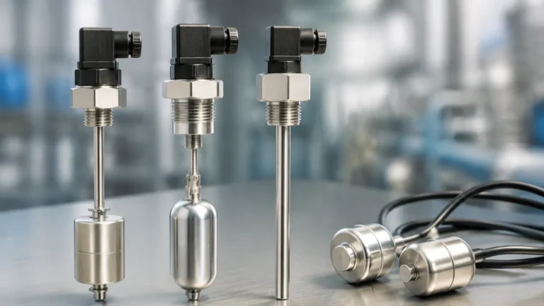
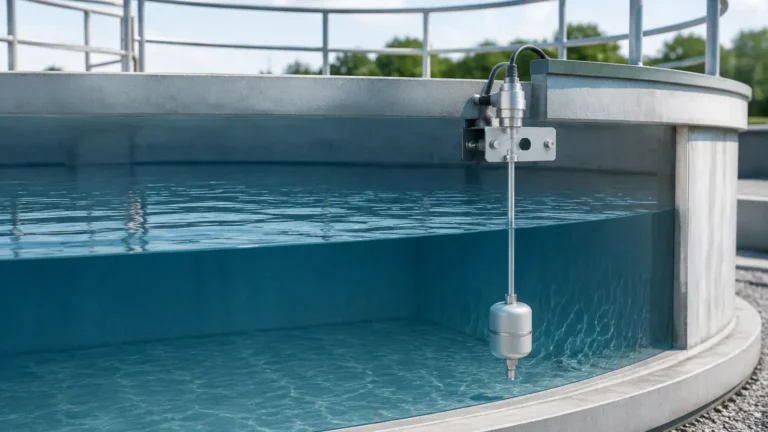
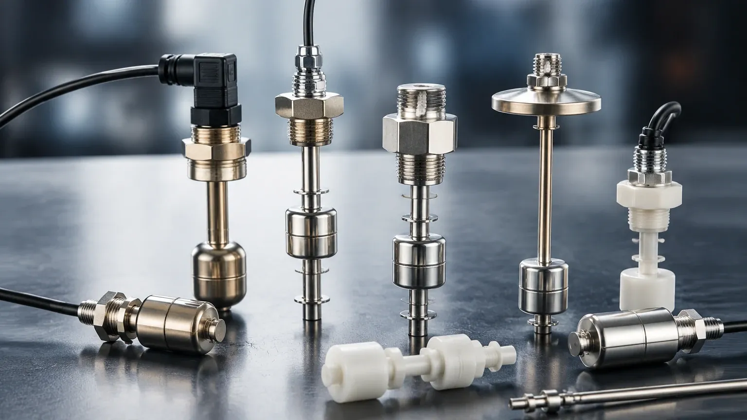
Float switches are the most traditional and widely used point-level sensors in the oil and gas industry. They operate on the principle of buoyancy. A float, containing an internal magnet, moves up and down a stem in response to the liquid level. When the float reaches a predetermined point, the magnetic field triggers a hermetically sealed reed switch located inside the stationary stem.
* Advantages: Simple, cost-effective, and requires no external power for the basic switch mechanism.
* Limitations: Susceptible to mechanical failure if the oil contains heavy particulates or if the oil's viscosity is high enough to "stick" the float to the stem.
2. Optical Level Switches
Optical sensors utilize an infrared LED and a phototransistor. When the sensor tip is in the air, the infrared light is reflected within a prism back to the receiver. When the tip is immersed in oil, the light is refracted into the liquid, causing the receiver to detect a change in light intensity, which triggers the switch.
* Advantages: Extremely compact, no moving parts, and very fast response times. They are ideal for clean oil applications where space is limited.
* Limitations: Performance can be degraded by highly reflective oils or heavy coating/filming on the sensor tip.
3. Capacitance Level Switches
Capacitance switches measure the change in electrical capacitance between the sensor probe and the tank wall (or a reference probe). Because oil is a non-conductive (dielectric) medium, its presence changes the dielectric constant of the environment around the probe. This shift in capacitance is processed by the electronics to signal a level change.
* Advantages: No moving parts and can be adjusted to ignore minor build-up on the probe.
* Limitations: Requires calibration for the specific dielectric constant of the oil being measured. If the oil type changes frequently, the switch may require recalibration.
4. Vibrating Fork (Tuning Fork) Switches
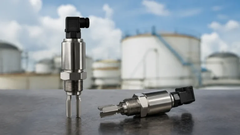
Vibrating fork Level Switches use a piezoelectric crystal to vibrate the tines at their natural resonant frequency. When the tines are immersed in oil, the frequency shifts or the vibration is damped. The internal electronics detect this change and switch the output.
* Advantages: Highly reliable, unaffected by bubbles, foam, or vibration in the tank. They are excellent for high-viscosity oils.
* Limitations: Typically more expensive than float or optical options; requires a minimum density to dampen the vibration effectively.
Key Evaluation Criteria for Oil Applications
When specifying oil level switches, several environmental and chemical factors must be considered to ensure long-term reliability.
Viscosity and Specific Gravity
Oil viscosity varies significantly with temperature. A heavy gear oil at 10°C behaves very differently than at 80°C. Mechanical float switches must have a float with a specific gravity lower than the oil (typically 0.6 to 0.8) to ensure it stays on the surface. For high-viscosity oils, non-mechanical types like vibrating forks are preferred to prevent mechanical sticking.
Dielectric Constant
For capacitance-based oil level switches, the dielectric constant (εr) is the most critical factor. Most industrial oils have a low dielectric constant, typically between 1.8 and 2.5. The sensor must be sensitive enough to detect these small changes against the background of air (εr = 1).
Temperature and Pressure
Oil systems often operate under high pressure (e.g., hydraulic systems at 200 bar / 20,000 kPa) or high temperatures (e.g., engine oil at 120°C). The housing material and seals (O-rings) must be compatible. Stainless steel (316L) is the standard for housings, while FKM (Viton) or PTFE is often required for seals to prevent degradation from chemical additives in synthetic oils.
Practical Selection Table
| Technology | Best For | Max Viscosity (cSt) | Pressure Resistance | Maintenance Need |
| :— | :— | :— | :— | :— |
| Float | Clean, low-viscosity fuels | < 100 | Moderate (up to 40 bar) | Medium (Mechanical) |
| Optical | Small reservoirs, clean oil | < 50 | High (up to 100 bar) | Low (Clean tip) |
| Capacitance | Coating-prone oils | < 2000 | High (up to 100 bar) | Low (Solid state) |
| Vibrating Fork | Heavy lubricants, foaming oil | < 10,000 | Very High (up to 160 bar) | Very Low |
Installation Guidelines and Considerations
Proper installation is as important as selecting the right technology. Incorrect placement often leads to false alarms or premature sensor failure.
1. Avoid Turbulence: Do not install the switch directly beneath an oil return line or near an agitator. The resulting turbulence can cause "chatter" in float switches or false damping in vibrating forks. If turbulence is unavoidable, use a stilling well (a bypass pipe) to stabilize the oil level around the sensor.
2. Orientation:
* Horizontal Mounting: Ideal for low-level alarms in small tanks. Ensure the cable entry points downward to prevent moisture from entering the housing via capillary action.
* Vertical Mounting: Preferred for high-level alarms or when multiple switch points are needed on a single stem (common in float-type switches).
3. No-Go Zones: Ensure the sensor is not placed in a "dead zone" where stagnant oil might accumulate and thicken, or where sludge might build up at the bottom of the tank.
4. Electrical Considerations: For hazardous environments (e.g., fuel oil storage), ensure the switch is rated as Intrinsically Safe (IS) or Explosion-Proof (Ex d). Always use shielded cables to prevent electromagnetic interference from nearby pumps or motors.
Limitations and Common Risks
While industrial oil level switches are robust, they are not immune to failure. Engineers should be aware of the following risks:
* Paraffin/Wax Build-up: In crude oil or certain fuel oils, paraffin can precipitate at lower temperatures, coating the sensor. This is particularly problematic for optical and capacitance sensors. In these cases, heated sensor tips or vibrating forks with high-torque tines are necessary.
* Aeration and Foaming: In high-speed hydraulic systems, oil can become aerated. This reduces the effective density of the fluid. A float switch calibrated for a specific gravity of 0.85 may sink if the "foamy" oil density drops to 0.70. Vibrating forks are generally the best solution for foamy media.
* Material Compatibility: Some synthetic oils contain aggressive additives that can swell standard NBR seals. Always verify the compatibility of the wetted materials with the specific oil's Safety Data Sheet (SDS).
Frequently Asked Questions (FAQs)
Q: Can I use a water level switch for oil?
A: Generally, no. Conductivity-based switches, which are common for water, will not work because oil is an insulator. Additionally, float switches designed for water (SG 1.0) may not float in lighter oils (SG 0.8).
Q: How do I handle oil that is very dark or opaque?
A: Avoid standard optical switches. While some high-power optical sensors can penetrate dark liquids, vibrating forks or capacitance switches are much more reliable for opaque oils.
Q: What is the best switch for a hydraulic power unit (HPU)?
A: For HPUs, a combination of a vibrating fork (for high-reliability low-level cutout) and a multi-point magnetic float switch (for general level monitoring) is a common engineering standard.
Q: How often should oil level switches be calibrated?
A: Float and vibrating fork switches typically require no calibration. Capacitance switches should be checked annually or whenever the oil specification is changed, as the dielectric constant may vary.
Conclusion
Selecting the right oil level switches involves balancing the physical properties of the oil with the mechanical and electrical constraints of the application. For clean, thin oils, simple float or optical sensors provide cost-effective point detection. For more demanding environments involving high viscosity, foam, or high pressure, vibrating fork and capacitance technologies offer the necessary durability. By adhering to strict installation standards and considering the specific gravity and dielectric constant of the media, operators can ensure the long-term protection of their industrial assets.