Level Switch Error Alma
Level Switch Error Alma
In industrial process control, the reliability of level detection is paramount to preventing tank overfills, pump cavitation, and dry-run conditions. When a system reports a "level switch error alma"—often referring to an active alarm (ALM) state or a specific fault condition within an electronic control unit—it indicates a breach in the expected operational logic. Understanding the root causes of these errors requires a deep dive into the measurement principles of level switches, the environmental factors affecting their performance, and the systematic approach to troubleshooting industrial instrumentation.
Understanding Industrial Level Switch Principles
Before addressing specific error states, it is essential to understand how different Level Switches function. Each technology has unique physical properties that dictate its susceptibility to certain types of errors.
Vibration (Tuning Fork) Switches
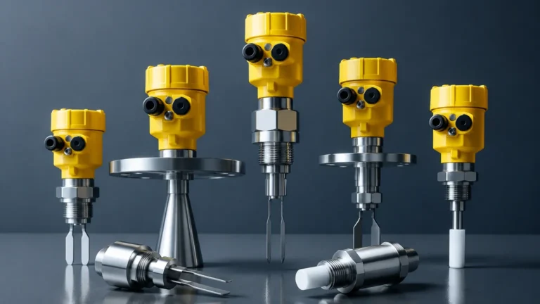
Vibrating level switches utilize a piezoelectric crystal to energize a tuning fork at its natural resonant frequency. When the fork is immersed in a medium (liquid or solid), the frequency shifts or the amplitude is dampened. The internal electronics detect this change and toggle the output. An "alma" or alarm error in these units often stems from internal crystal failure or excessive material buildup that prevents the fork from vibrating even when the tank is empty.
Float and Displacement Switches
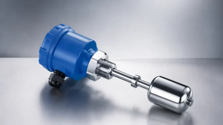
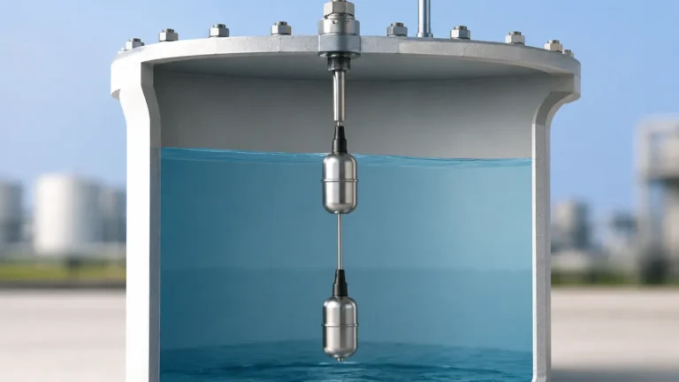
These mechanical switches rely on buoyancy. A float moves with the liquid level, eventually triggering a reed switch or a microswitch via a magnetic sleeve. Errors here are typically mechanical, such as a stuck float due to scaling or a collapsed float caused by pressure surges exceeding the design limit (e.g., above 40 bar).
Capacitance Level Switches
Capacitance switches treat the sensor probe and the vessel wall as two plates of a capacitor. The medium acts as the dielectric. As the level rises, the capacitance changes. These are highly sensitive but prone to errors if the dielectric constant of the medium fluctuates significantly or if there is conductive coating on the probe.
Decoding the Level Switch Error Alma
The term "alma" in a B2B engineering context usually refers to the "Alarm" (ALM) status indicator on a digital controller or a distributed control system (DCS) interface. When a level switch triggers an error alarm, it is often categorized into one of three states:
1. Process Alarm: The level has reached a predefined high-high (HH) or low-low (LL) limit. This is a functional alarm rather than a hardware fault.
2. Hardware Fault: The self-diagnostics of the switch have detected an internal failure, such as a broken wire, a short circuit, or a damaged sensing element.
3. Signal Out of Range: The transmitter is sending a current signal (typically outside the 4-20 mA range, such as <3.6 mA or >21 mA) indicating a "bad PV" (Process Variable) status.
In systems where "Alma" specifically refers to an alarm module or a localized control logic error, the technician must verify if the switch is in a "fail-safe" mode. Fail-safe high (FSH) ensures the switch indicates a full state upon power loss, while fail-safe low (FSL) indicates an empty state.
Common Root Causes for Level Switch Failures
Identifying why a level switch error occurs requires analyzing the interaction between the instrument and the process environment. Below are the primary technical drivers of frequent alarms.
Material Buildup and Coating
In industries like wastewater treatment or chemical processing, media can adhere to the sensing element. For tuning fork switches, a thick coating can "bridge" the forks, mimicking the presence of liquid. For capacitance probes, conductive buildup creates a false path to the ground, triggering a permanent alarm state.
Turbulence and Foam
High-speed agitators or aggressive inflow can create surface turbulence. Mechanical float switches may bounce, causing "chatter" in the relay. Furthermore, many switches struggle to distinguish between a true liquid level and a layer of foam. If the foam is dense enough to dampen a tuning fork but the process requires detection of the liquid underneath, an error in logic occurs.
Electrical Interference (EMI)
Long cable runs without proper shielding can pick up electromagnetic interference from nearby Variable Frequency Drives (VFDs) or high-voltage motors. This interference can corrupt the signal reaching the control room, manifesting as a "level switch error alma" on the HMI (Human Machine Interface).
Selection Criteria to Minimize Operational Errors
Selecting the correct technology is the most effective way to prevent recurring errors. Engineers should evaluate the media properties and vessel conditions against the switch specifications.
| Technology | Best For | Limitations | Pressure/Temp Limits (Typical) |
| :— | :— | :— | :— |
| Tuning Fork | Liquids, powders, granules | High viscosity, heavy coating | Up to 160 bar / 250°C |
| Float Switch | Clean liquids, water tanks | Moving parts, buildup-prone | Up to 40 bar / 150°C |
| Capacitance | Corrosive chemicals, interface | Dielectric changes | Up to 100 bar / 200°C |
| Ultrasonic Gap | Non-contact, clean liquids | Foam, heavy vapors | Up to 20 bar / 100°C |
When specifying a switch, always confirm the Specific Gravity (SG) of the liquid. A float designed for water (SG 1.0) will fail to rise in a light hydrocarbon (SG 0.7), leading to a permanent low-level error.

Installation Best Practices for Reliable Performance
Many errors attributed to the device are actually the result of improper installation. Adhering to the following guidelines ensures the switch operates within its factual boundaries:
* Avoid the Inflow Stream: Never install a level switch directly beneath a filling pipe. The force of the falling material can damage the probe or cause false triggers.
* Nozzle Length: For tuning fork switches, ensure the forks extend fully into the vessel. If the forks remain inside a narrow mounting nozzle, material can become trapped, leading to a false high alarm.
* Orientation: Install horizontal switches with a slight downward angle (approx. 5 degrees) to allow liquid to drain off the sensing element, reducing the risk of coating-induced errors.
* Grounding: Ensure the instrument housing is properly grounded to the vessel, especially for capacitance and RF admittance switches, to provide a stable reference point for measurement.
Troubleshooting and Maintenance Procedures
When a "level switch error alma" is reported, follow this systematic diagnostic checklist:
1. Visual Inspection: Check for physical damage to the probe or housing. Remove the switch to inspect for material buildup or corrosion.
2. Loop Test: Use a multimeter to check the continuity of the switch contacts. For 4-20 mA loop-powered switches, verify the current output. A reading of 0 mA usually indicates a broken wire, while a reading of 22 mA indicates a hardware fault.
3. Bench Calibration: If the switch is adjustable (like many capacitance or ultrasonic models), test it in a controlled environment with a sample of the actual process media. Adjust the sensitivity (potentiometer or digital menu) to ensure it ignores foam or light coating.
4. Power Supply Check: Ensure the voltage at the instrument terminals matches the nameplate requirements (e.g., 24V DC or 110/220V AC). Low voltage can cause intermittent electronics failure and erratic alarm states.
Limitations of Point Level Detection
While level switches are robust, they have inherent limitations. They provide "point" detection (on/off) rather than continuous measurement. If a process requires knowing the exact percentage of tank volume, a radar or ultrasonic level transmitter should be used in conjunction with a switch. Furthermore, switches with moving parts (floats) have a finite mechanical lifespan, typically rated in hundreds of thousands of cycles, after which the risk of a mechanical "alma" error increases significantly.
Frequently Asked Questions (FAQ)
Q: Can a level switch error be caused by ambient temperature changes?
A: Yes. Extreme temperature fluctuations can cause condensation inside the housing if the cable glands are not properly sealed. This moisture can short-circuit the electronics, triggering an alarm.
Q: How do I distinguish between a "Real" alarm and a "False" error?
A: A real alarm coincides with the actual level reaching the sensor. A false error occurs when the sensor triggers while the level is clearly away from the probe. Cross-referencing with a manual sight glass or a secondary level transmitter is the best way to verify.
Q: What is the significance of the "test" button found on some level switches?
A: The test button manually interrupts the circuit or simulates a dampened frequency to verify that the output relay and the downstream alarm logic (the "alma" system) are functioning correctly without needing to fill the tank.
Q: Why does my tuning fork switch work in water but fail in oil?
A: Oil has a different density and viscosity than water. While most tuning forks are designed for a wide range of densities (often down to 0.5 g/cm³), extremely low-density fluids may not provide enough damping to trigger the switch, leading to a "fail to detect" error.
For engineers and plant operators, resolving a level switch error alma involves more than just resetting a controller. It requires a technical audit of the device selection, the installation environment, and the electrical integrity of the control loop. By matching the right Level Switches to the specific application and following rigorous maintenance protocols, facilities can ensure maximum uptime and safety.