Level Switch Electrical Symbol
Level Switch Electrical Symbol
In industrial automation and process control, the ability to accurately interpret technical documentation is a fundamental requirement for engineers, electricians, and system integrators. Among the various components found on Piping and Instrumentation Diagrams (P&IDs) and electrical schematics, the level switch electrical symbol plays a critical role. It serves as the universal language that defines how a device detects the presence or absence of a substance at a specific point and how it communicates that state to a control system.
Level switches are discrete sensors used to trigger alarms, control pumps, or provide safety interlocks. Understanding the nuances of the level switch electrical symbol is essential for ensuring that the physical installation matches the design intent, preventing costly overflows, dry-run conditions, or system failures. This guide provides a comprehensive technical overview of level switch symbols, their underlying principles, and practical application in industrial environments.
Measurement Principles and Device Logic
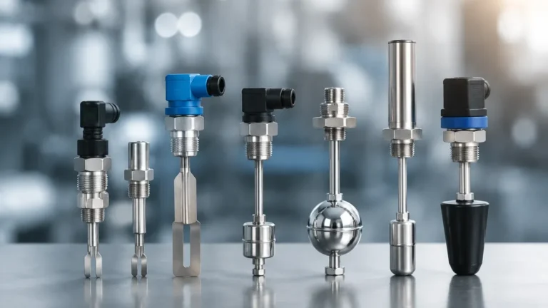
Before delving into the specific symbols used in schematics, it is necessary to understand the measurement principles of various Level Switches. The physical method of detection often dictates how the device is wired and represented in a circuit.
Mechanical and Float Switches
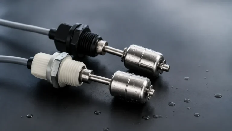
Float switches operate on the principle of buoyancy. A float containing a magnet moves with the liquid level, actuating a reed switch or a microswitch when it reaches a predetermined point. In electrical drawings, these are often represented by a standard switch contact modified with a float-shaped graphic (typically a small circle or ball).
Vibrating Tuning Fork Switches
These electronic switches use a piezoelectric crystal to vibrate a metal fork at its natural frequency. When the fork is immersed in a liquid or solid, the frequency changes. The internal electronics detect this shift and switch an output. Because these require power to operate, their electrical symbol often includes terminals for a power supply in addition to the switching contacts.
Capacitive Level Switches
Capacitive sensors measure the change in capacitance between a probe and the tank wall (or a reference electrode). As the medium covers the probe, the dielectric constant changes, triggering the switch. These are common in both liquid and bulk solid applications. Their symbols may include a capacitor-like element to denote the sensing technology.
Ultrasonic and Radar Switches
While often used for continuous measurement, these technologies can also function as point-level switches. They use time-of-flight principles, emitting a pulse and measuring the time it takes for the reflection to return. These are highly sophisticated and usually represented as complex blocks in electrical schematics rather than simple contact symbols.
Standard Symbols in Industrial Schematics
Electrical symbols are standardized to ensure consistency across international borders. The two most common standards are IEC 60617 (International Electrotechnical Commission), widely used in Europe and Asia, and ANSI/IEEE (American National Standards Institute), common in North America.
IEC 60617 Symbols
In the IEC system, a level switch is typically represented by a functional symbol combined with a qualifying letter. The letter "L" denotes level. A point-level switch is often shown as a contact with a specific "flag" or graphic indicating it is actuated by fluid level.
* High Level Switch (LSH): The symbol indicates a contact that changes state when the level rises to a specific point.
* Low Level Switch (LSL): The symbol indicates a contact that changes state when the level falls below a specific point.
ANSI/IEEE Symbols
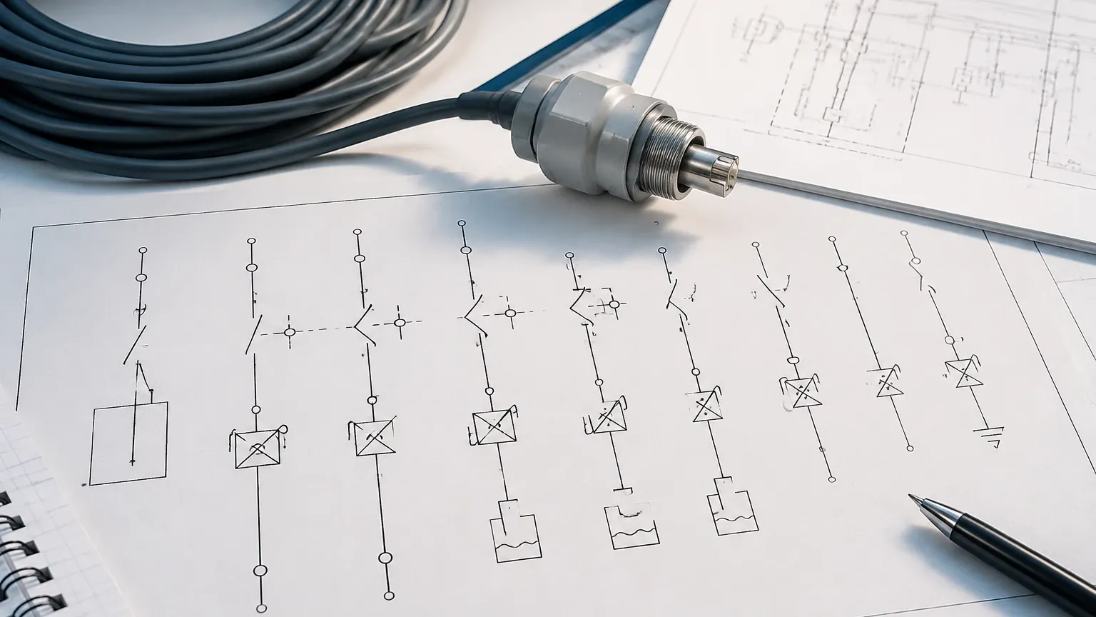
ANSI symbols often use a more pictorial approach. A level switch might be shown as a standard toggle switch with a small circle (the float) attached to the lever. The orientation of the float indicates whether it is a high-level or low-level device.
P&ID vs. Electrical Schematics
It is important to distinguish between a P&ID symbol and an electrical schematic symbol.
* P&ID Symbol: Usually a circle containing letters like "LSH" (Level Switch High) or "LSLL" (Level Switch Low Low), connected to the process vessel by a line.
* Electrical Symbol: Shows the actual wiring terminals, the type of contact (Normally Open or Normally Closed), and the power requirements.
Contact Configurations and Terminal Logic
The level switch electrical symbol must clearly communicate the state of the switch in its "de-energized" or "shelf" state. This is vital for fail-safe design.
Normally Open (NO)
In a Normally Open configuration, the circuit is open (no current flows) when the switch is not actuated. For a high-level float switch, "not actuated" means the liquid is below the float. When the liquid rises and lifts the float, the contact closes.
Normally Closed (NC)
In a Normally Closed configuration, the circuit is closed when the switch is not actuated. If the level reaches the trip point, the contact opens. This is often preferred for safety-critical applications because a broken wire will be detected as a trip (fail-safe).
Single Pole Double Throw (SPDT)
Many industrial level switches from manufacturers like Welk feature SPDT contacts. The symbol for an SPDT switch shows one common terminal (COM) and two possible paths: one Normally Open (NO) and one Normally Closed (NC). This allows the user to choose the logic required for their specific control system.
| Contact Type | Symbol Description | Typical Application |
| :— | :— | :— |
| NO (Normally Open) | Two parallel lines with a diagonal gap. | Pump start on high level. |
| NC (Normally Closed) | A continuous line with a break that is bridged by a bar. | High-level alarm/Overfill prevention. |
| SPDT | A single input branching into two output options. | Versatile control and signaling. |
| DPDT | Two independent SPDT switches actuated by one mechanism. | Redundant control and local indication. |
Practical Selection and Technical Specifications
When selecting Level Switches based on their electrical symbols and specifications, engineers must consider the electrical load and the environment. Welk provides a range of instruments designed for diverse industrial needs, from water treatment to chemical processing.
Electrical Load Ratings
It is a common error to ignore the current and voltage ratings shown near the level switch electrical symbol.
* Dry Contacts: These are voltage-free contacts. They do not provide power but simply open or close a circuit. They are typically rated for low current (e.g., 2A at 250VAC).
* Electronic Outputs: Modern switches may provide PNP/NPN transistor outputs or a 4-20mA current loop. These require specific DC power supplies (usually 24VDC).
Environmental Protection
The symbol in a drawing may also be accompanied by a rating for the enclosure. For example, an "Ex" symbol indicates the switch is rated for hazardous (explosive) areas. In metric-standard regions, IP (Ingress Protection) ratings such as IP65 or IP67 are standard to define resistance to dust and water.
Installation and Wiring Considerations
Properly translating a level switch electrical symbol into a physical installation requires attention to detail.
1. Terminal Identification: Always match the wire numbers in the schematic to the terminal numbers on the device. Welk level switches typically feature clearly labeled terminals (e.g., 1, 2, 3 or COM, NO, NC).
2. Cable Selection: For electronic switches (tuning fork or capacitive), shielded cables are often recommended to prevent electromagnetic interference (EMI) from affecting the signal.
3. Conduit Entries: Ensure that conduit entries are sealed to prevent moisture from entering the housing, which can lead to short circuits—a condition not shown on a symbol but critical in practice.
4. Mounting Orientation: Some symbols imply a specific mounting (e.g., top-mounted vs. side-mounted). A float switch designed for horizontal mounting will have a different actuation logic than one designed for vertical mounting.
Limitations and Common Risks
Misinterpreting a level switch electrical symbol can lead to significant operational risks.
* Inverted Logic: The most common mistake is confusing NO and NC contacts. In a high-level alarm application, using an NO contact instead of an NC contact could mean the system fails to alarm if a wire is cut, leading to a tank overflow.
* Hysteresis Overlook: While a symbol shows a single point of action, all mechanical switches have hysteresis (the difference between the switch-on and switch-off points). For example, a switch might close at 1000mm but not open again until the level drops to 980mm.
* Contact Pitting: Using a switch to directly drive a high-power motor (without a relay or contactor) can cause the contacts to weld together. The symbol represents the switch logic, not necessarily its ability to handle high inductive loads.
Frequently Asked Questions (FAQ)
Q: What does the 'L' stand for in a level switch symbol?
A: In both P&ID and electrical standards, 'L' stands for Level. It is often followed by 'S' for Switch, and then 'H' (High), 'L' (Low), 'HH' (High-High), or 'LL' (Low-Low) to indicate the setpoint.
Q: Can I use a level switch electrical symbol for both liquids and solids?
A: Yes, the basic symbol for a level switch is generally the same regardless of the medium. However, the technical specifications for the device (such as a vibrating probe for solids vs. a float for liquids) must be verified against the project requirements.
Q: How do I represent a multi-point level switch?
A: A multi-point switch is represented by multiple contact symbols within a single enclosure box on the schematic, each labeled with its respective trip level (e.g., Point 1: 500mm, Point 2: 1500mm).
Q: Why do some symbols show a power supply connection?
A: Simple reed-based float switches are passive and don't need power. However, active technologies like ultrasonic, radar, and tuning fork switches require external power (typically 24VDC or 110/230VAC) to operate their internal electronics. This is shown as additional terminals on the electrical symbol.
Conclusion
The level switch electrical symbol is a vital component of industrial design, providing the necessary clarity for safe and efficient process control. By understanding the relationship between the physical measurement principle and the symbolic representation, engineers can ensure that their systems are robust and maintainable. When sourcing Level Switches, it is essential to consult the manufacturer's data sheets to confirm that the electrical characteristics and contact logic align perfectly with the schematic design. Whether managing water treatment facilities or complex chemical reactors, the precise application of these symbols remains a cornerstone of professional engineering practice.