Level Switch High Symbol
Level Switch High Symbol
In industrial process control, the accurate representation and identification of instrumentation are critical for safety, maintenance, and system design. Among the most vital components in any fluid handling system is the level switch, specifically those designated for high-level detection. The term "level switch high symbol" refers to the standardized graphical representation used in Process and Instrumentation Diagrams (P&ID) to denote a device intended to trigger an action or alarm when a liquid or solid reaches a specific upper threshold.
Understanding these symbols, alongside the underlying measurement principles of the hardware they represent, is essential for engineers, technicians, and system integrators. This guide explores the technical aspects of high-level switches, their symbolic representation in engineering documentation, and practical considerations for their application in industrial environments.
Understanding Level Switch Technology and High-Level Detection
Before diving into the specifics of the level switch high symbol, it is necessary to understand the functional role of a high-level switch. In a process vessel or tank, "Level Switch High" (LSH) is typically used to indicate that the tank is nearly full. This signal may be used to stop a pump, close an inlet valve, or trigger an operator alert. In more critical applications, a "Level Switch High High" (LSHH) is employed as a redundant safety measure to prevent catastrophic overfills or environmental spills.
Core Measurement Principles
Level switches operate on various physical principles, each suited to different media and environmental conditions.
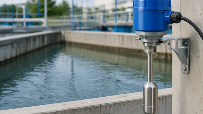
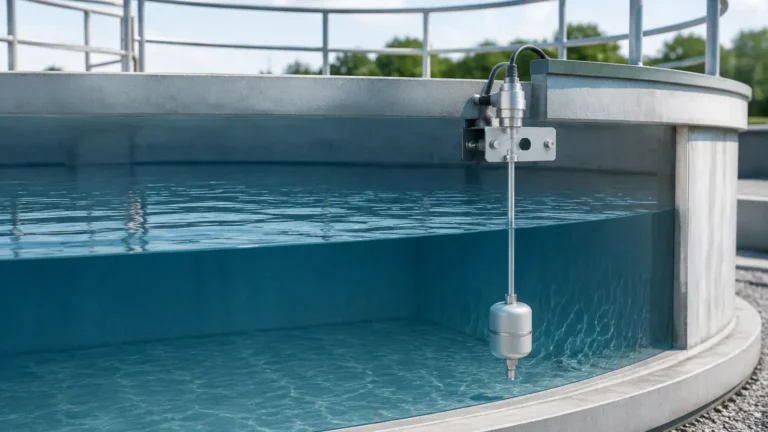
1. Buoyancy (Float Switches): This is the most traditional method. A float containing a magnet moves with the liquid level. When the float reaches a predetermined height, the magnetic field actuates a reed switch or a microswitch. This is a simple, mechanical approach often used in water treatment and basic chemical storage.
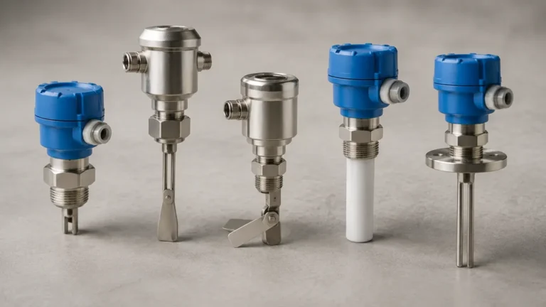
2. Vibration (Tuning Fork Switches): These switches feature a fork-shaped sensing element that vibrates at its natural resonance frequency in the air. When the liquid reaches the fork, the frequency changes or the vibration is damped. The electronics detect this shift and switch the output. These are highly reliable for liquids and granulates and are less affected by turbulence or bubbles.
3. Capacitance: These sensors measure the change in electrical capacitance between the probe and the tank wall (or a reference probe). As the medium covers the probe, the dielectric constant changes, triggering the switch. This method is effective for both liquids and solids but requires calibration based on the material's dielectric properties.
4. Conductivity: Used primarily for conductive liquids like water or acids. When the liquid touches the electrode, an electrical circuit is completed between the electrode and the vessel wall (or another electrode), triggering the switch.
5. Ultrasonic: These switches emit a high-frequency sound wave across a gap in the sensor. When the gap is filled with liquid, the sound transmission changes, signaling the level. This is a non-contact or gap-contact method useful for various chemical applications.
For a comprehensive overview of hardware options, engineers often consult professional manufacturers like Welk to match the technology to the specific chemical or physical properties of the media. You can Review product options and application support to see how these principles are implemented in industrial-grade hardware.
The Role of the Level Switch High Symbol in P&ID
The level switch high symbol is governed by international standards, most notably ISA-5.1 (Instrumentation Symbols and Identification). These standards ensure that an engineer in Europe can understand a diagram produced in North America or Asia without ambiguity.
Anatomy of the Symbol
In a P&ID, a level switch is represented by a circle (often called a "bubble"). Inside this circle, letter codes define the function of the instrument. For a high-level switch, the standard notation is LSH.
* L (First Letter): Denotes the measured variable, which is "Level."
* S (Succeeding Letter): Denotes the function, which is "Switch."
* H (Succeeding Letter): Denotes the initiated action or the state, which is "High."
If the switch is intended for an emergency shutdown or an extra-high alarm, the symbol will read LSHH (Level Switch High High).
Graphical Variations
The bubble itself provides information about the device's location:
* A simple circle: Indicates the instrument is field-mounted (located at the tank or process area).
* A circle with a solid horizontal line: Indicates the instrument (or its readout/control) is located in a primary control room or a central control panel accessible to the operator.
* A circle with a dashed horizontal line: Indicates the instrument is located in a secondary or local panel, often not directly visible to the main operator.
In some diagrams, a small line or arrow may extend from the bubble to the process line or vessel, indicating the exact point of connection. The "High" designation tells the reader that the switch's logic is configured to change state when the level rises above the setpoint.
Common Technologies for High-Level Switching
Choosing the right technology for an LSH application depends on the medium's density, viscosity, temperature, and pressure. The following table summarizes common technologies used for high-level detection.
| Technology | Typical Media | Advantages | Limitations |
| :— | :— | :— | :— |
| Tuning Fork | Liquids, Powders | No calibration needed; ignores foam. | Not for very high-viscosity media. |
| Float Switch | Water, Oils | Low cost; simple installation. | Moving parts can jam; sensitive to debris. |
| Capacitance | Chemicals, Solids | Handles high temperatures/pressures. | Requires calibration; sensitive to coating. |
| Conductive | Acids, Water | No moving parts; very compact. | Only for conductive liquids; probe corrosion. |
| Ultrasonic | Clean Liquids | Non-contact options available. | Sensitive to surface turbulence and foam. |
Tuning Fork Switches in High-Level Logic
Vibrating level switches are frequently used as the physical hardware behind the level switch high symbol in modern plants. Because they do not require calibration and are virtually maintenance-free, they are the preferred choice for overfill protection. In a P&ID, if a tuning fork switch is used for high-level detection, it is still labeled LSH, though a separate instrument index will specify the model and technology.
Selection Criteria for High-Level Monitoring
When transitioning from a P&ID symbol to a physical installation, several technical criteria must be evaluated to ensure the LSH functions as intended.
1. Media Compatibility: The wetted parts of the switch (e.g., Stainless Steel 316L, PTFE, or Hastelloy) must be resistant to the process fluid. For example, a conductive probe in a corrosive acid tank must be made of a compatible alloy or coated.
2. Process Conditions: Ensure the switch can withstand the maximum operating pressure (e.g., 40 bar) and temperature (e.g., 150°C / 302°F).
3. Output Type: High-level switches typically offer relay outputs (SPDT/DPDT), PNP/NPN transistors, or two-wire signals (8/16mA). The choice depends on the PLC or DCS requirements.
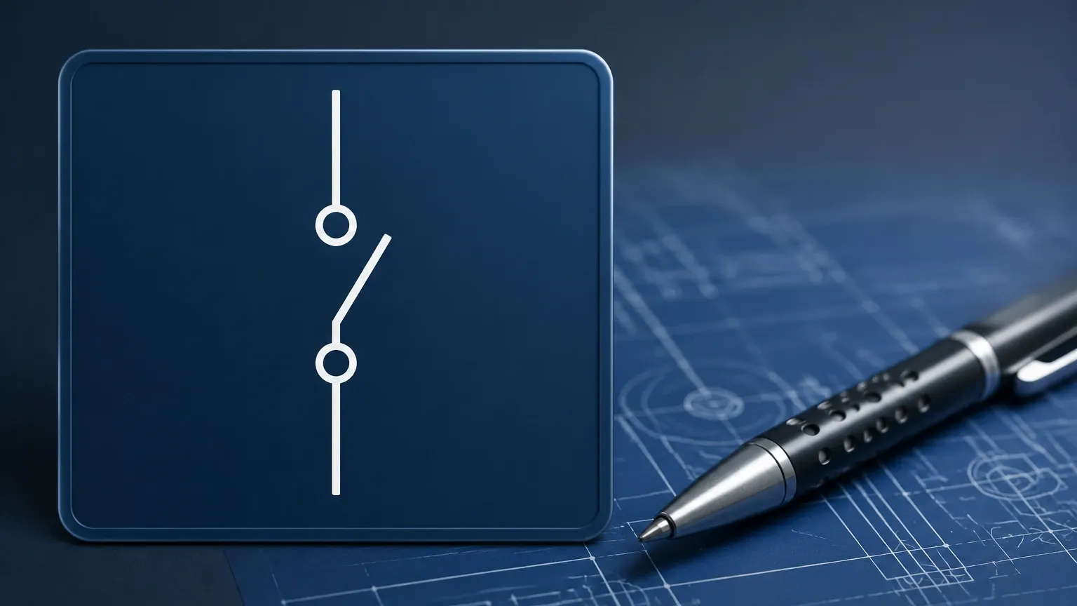
4. Fail-Safe Mode: For high-level applications, the switch should be configured to a "Fail-Safe High" mode. This means the circuit is closed when the level is low and opens when the level is high or if power is lost. This ensures that a broken wire is interpreted as a high-level condition, preventing an accidental overfill.
Installation Guidelines for Reliable High-Level Detection
The physical placement of the device represented by the level switch high symbol is as important as the device itself. Incorrect mounting can lead to false alarms or, worse, a failure to trigger during an overfill.
* Avoid Turbulence: Do not install the switch directly under a fill pipe. The falling liquid can cause mechanical wear on floats or false damping on tuning forks. If placement near an inlet is unavoidable, use a baffle or a stilling well.
* Nozzle Length: Ensure the sensing element (the fork or the probe) extends sufficiently into the vessel. If the nozzle is too long, material may build up inside the nozzle and cause the switch to stay in the "High" state even after the level has dropped.
* Orientation: Most tuning fork and float switches can be mounted horizontally or vertically. However, for high-level detection, horizontal mounting at the exact trip point is common to provide a precise trigger level. For vertical mounting, the stem length must be specified to reach the desired high-level setpoint (e.g., 500mm from the tank top).
* Clearance: Maintain at least 50mm (approx. 2 inches) of clearance from the tank wall or any internal structures like agitators or heating coils to avoid interference.
Limitations and Maintenance of Level Switches
While Level Switches are designed for reliability, they are not immune to environmental challenges.
* Coating and Build-up: In sticky or viscous media, material can accumulate on the sensor. While tuning forks have some immunity to coating, excessive build-up can eventually cause a false "High" signal. Regular inspection is required in these applications.
* Foam: Some technologies, like ultrasonic or standard capacitance, may struggle to distinguish between a layer of foam and the actual liquid level. If foam is present, tuning forks or specialized "foam-blind" capacitance probes are recommended.
* Electrical Interference: Ensure proper shielding of cables, especially for capacitance and ultrasonic switches, to prevent electromagnetic interference (EMI) from large motors or variable frequency drives (VFDs) from causing signal noise.
Maintenance Checklist
1. Functional Test: Periodically raise the liquid level or manually actuate the switch to verify the alarm triggers in the control room.
2. Visual Inspection: Check for corrosion on the housing and wetted parts.
3. Seal Integrity: Inspect cable glands and housing gaskets to ensure no moisture has entered the electronics compartment.
Frequently Asked Questions
Q: What is the difference between LSH and LSHH?
A: LSH (Level Switch High) is typically a functional alarm used to manage the process (e.g., stop a pump). LSHH (Level Switch High High) is a safety-critical alarm, often part of a Safety Instrumented System (SIS), designed to prevent a disaster if the LSH fails.
Q: Can a single instrument represent both LSH and LSL (Level Switch Low)?
A: Generally, no. A point level switch triggers at one specific location. To have both high and low signals, you typically need two separate switches or a single continuous level transmitter with programmed switch points in the controller.
Q: Does the level switch high symbol change if the switch is pneumatic instead of electrical?
A: The core letters (LSH) remain the same, but the lines connecting the bubble to other components will change. A solid line represents an electrical signal, while a line with double cross-marks represents a pneumatic signal.
Q: Why is my high-level switch not resetting after the level drops?
A: This is often caused by "hysteresis" settings or material build-up. If it is a float switch, the float may be stuck. If it is a tuning fork or capacitance probe, check for material bridging between the probe and the tank wall.
By adhering to standardized symbols and selecting the appropriate measurement technology, industrial facilities can ensure their level control systems are both safe and efficient. Whether designing a new P&ID or troubleshooting an existing tank farm, the clarity provided by the level switch high symbol is the first step toward operational excellence.