Level Switch Hydac
Level Switch Hydac
In the realm of hydraulic and lubrication technology, maintaining the correct fluid level is not merely a matter of operational efficiency but a fundamental requirement for system safety. A level switch hydac, and similar industrial-grade level monitoring devices, serve as the primary line of defense against pump cavitation, oil starvation, and environmental contamination caused by overflows. These components are designed to withstand the rigorous conditions of hydraulic power units (HPUs), where high temperatures, vibrations, and specific fluid chemistries are the norm.
Understanding the mechanics, selection criteria, and installation nuances of these switches allows engineers to specify the most reliable solution for their specific application. This guide explores the engineering principles behind level switches used in fluid power and provides a framework for selecting the appropriate technology for industrial reservoirs.
Measurement Principles of Level Switches
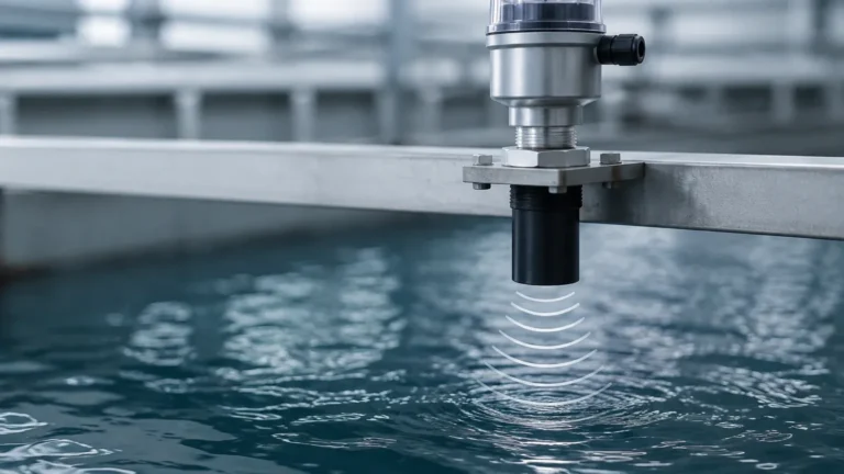
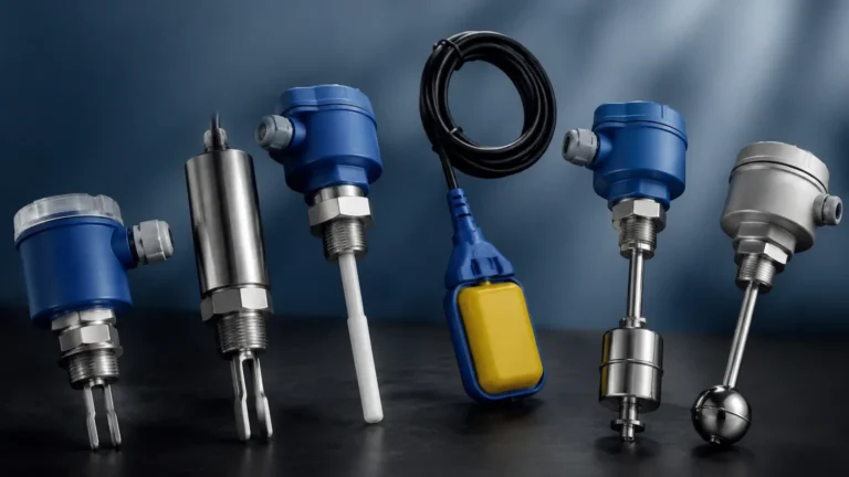
Before selecting a specific model, it is essential to understand the physical principles that govern level detection. In hydraulic and industrial automation, three primary methods are commonly employed: magnetic float, capacitive, and electronic (often utilizing ultrasonic or hydrostatic pressure for continuous monitoring with switch outputs).
Magnetic Float Principle
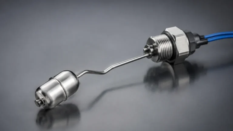
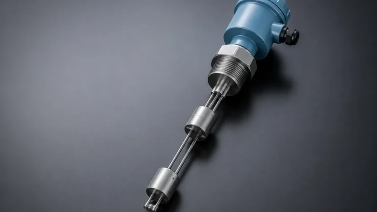
This is the most common technology found in a standard level switch hydac configuration. It relies on a float containing a permanent magnet that moves along a guide tube. Inside the tube, one or more reed contacts are positioned at specific heights. As the fluid level changes, the float moves the magnet past the reed switch, causing the contact to open or close.
* Advantages: Simple, reliable, and requires no external power to operate the basic switch contact.
* Limitations: Susceptible to mechanical sticking if the fluid is heavily contaminated with magnetic particles.
Capacitive Principle
Capacitive level switches measure the change in electrical capacitance between two electrodes (or one electrode and the tank wall) caused by the presence of the fluid. Since hydraulic oils have a different dielectric constant than air, the sensor can detect when it is submerged.
* Advantages: No moving parts, making them ideal for high-vibration environments.
* Limitations: Requires calibration for different fluid types and can be affected by heavy coating or foam.
Electronic and Multi-Point Sensing
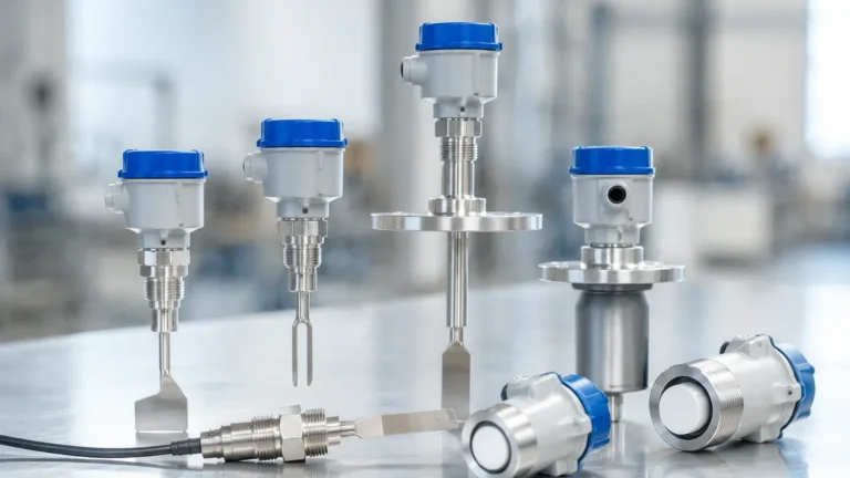
Modern industrial Level Switches often combine level sensing with temperature monitoring. These electronic units may use high-frequency signals or integrated microprocessors to provide digital displays and adjustable switching points via a control panel or IO-Link interface.
The Role of Level Switches in Hydraulic Systems
In a hydraulic reservoir, the fluid level is dynamic. It drops as cylinders extend and rises as they retract. A level switch must be configured to account for these fluctuations while still protecting the system.
1. Low Level Warning: Alerts the operator that the fluid is reaching a minimum threshold, often due to a slow leak.
2. Low Level Shutdown: A critical safety setpoint that de-energizes the pump motor to prevent cavitation. Cavitation occurs when the pump cannot draw enough fluid, leading to the formation of vapor bubbles that implode and cause catastrophic internal damage.
3. High Level Warning: Prevents overfilling during maintenance or detects internal heat exchanger leaks where coolant might be entering the oil reservoir.
Technical Specifications and Selection Criteria
When evaluating a level switch hydac or a Welk industrial level sensor, several technical parameters must be cross-referenced with the application's requirements. The following table outlines the primary considerations for hydraulic fluid applications.
Selection Table: Industrial Level Switch Parameters
| Parameter | Requirement | Notes |
| :— | :— | :— |
| Fluid Compatibility | Mineral oils, HFC, HEES, Water-glycol | Ensure seal materials (Viton/FKM, NBR) match the fluid. |
| Operating Pressure | Typically 1 to 10 bar (14.5 to 145 psi) | Most reservoir switches are for non-pressurized tanks. |
| Temperature Range | -20°C to +80°C (-4°F to +176°F) | High-temperature versions are required for specialized HPUs. |
| Switching Logic | N/O, N/C, or Change-over | N/C (Normally Closed) is preferred for "fail-safe" low-level detection. |
| Mounting Type | Flange, Threaded (G-thread, NPT) | Top-mounting is standard for hydraulic reservoirs. |
| Electrical Connection | M12, DIN 43650, or Cable lead | M12 is becoming the industry standard for sensor integration. |
| Probe Length | 100 mm to 1500 mm | Must be sized to the specific tank depth and critical oil levels. |
Installation Considerations for Hydraulic Reservoirs
Proper installation is as critical as selecting the right hardware. Incorrect placement can lead to false positives or mechanical failure of the switch.
Avoiding Turbulence
In hydraulic tanks, the return line often creates significant turbulence and aeration. If a float-style level switch is placed too close to a return line, the moving fluid can cause the float to bounce, leading to "chatter" in the electrical signal. This can damage contactors and trigger unnecessary alarms.
* Solution: Install the switch behind a baffle plate or use a stilling well (a perforated tube that surrounds the float) to dampen fluid movement.
Vertical Alignment
Float switches must be installed vertically. A deviation of more than 15° from the vertical axis can increase friction between the float and the guide tube, potentially causing the float to stick.
Magnetic Interference
Hydraulic systems often generate metallic wear particles. While filters remove most of these, some may bypass and cling to the magnetic float of a level switch. Regular inspection is required, or the use of a capacitive switch should be considered if magnetic debris is a chronic issue.
Limitations and Potential Risks
While highly reliable, level switches are not "set and forget" components. Engineers should be aware of the following risks:
1. Viscosity Impacts: In extremely cold environments, hydraulic oil viscosity increases significantly. A lightweight float may struggle to move through thick oil, delaying the response time of the switch during a cold start.
2. Contact Rating: Reed switches have limited current-carrying capacity. They should never be used to power a motor or a large solenoid directly. Instead, they should trigger a high-impedance PLC input or a secondary relay.
3. Foaming: If the hydraulic oil is aerated and forms a thick layer of foam, some level switches (particularly capacitive or ultrasonic types) may struggle to distinguish between the foam and the actual liquid level.
Maintenance and Troubleshooting
A proactive maintenance schedule ensures the longevity of the level monitoring system. For a level switch hydac or similar industrial unit, the following steps are recommended:
* Annual Function Test: Manually lift the float (if accessible) or partially drain the reservoir to ensure the switch triggers the correct alarm or shutdown sequence.
* Electrical Inspection: Check M12 connectors or junction boxes for signs of moisture ingress or oil wicking, which can cause short circuits.
* Cleaning: For capacitive probes, ensure there is no buildup of oxidized oil or varnish, which can change the dielectric properties sensed by the device.
Frequently Asked Questions (FAQ)
Q: Can I use a level switch designed for water in a hydraulic oil tank?
A: Generally, no. The specific gravity of hydraulic oil (approx. 0.85 to 0.90) is lower than water (1.0). A float designed for water may not have enough buoyancy to rise in oil. Additionally, the seal materials (like EPDM) used in water applications may swell and fail when exposed to mineral oils.
Q: What is the benefit of a switch with a built-in temperature sensor?
A: Space on a reservoir top is often limited. Combining level and temperature sensing into a single process connection reduces the number of holes that need to be drilled/tapped in the tank and simplifies the wiring harness.
Q: How do I choose between a fixed-length switch and an adjustable one?
A: Fixed-length switches are more robust and cost-effective for high-volume OEM machinery where the tank design is finalized. Adjustable switches are better for prototypes or facilities where one switch model might be kept as a spare for multiple different tank sizes.
Q: Is IO-Link necessary for a simple level switch?
A: While not necessary for a simple on/off signal, IO-Link allows for remote parameterization, continuous level reporting, and diagnostic data (such as internal temperature or operating hours), which supports Industry 4.0 and predictive maintenance goals.
Conclusion
Selecting a level switch hydac or an equivalent industrial Level Switches solution requires a thorough understanding of the fluid dynamics within the reservoir. By prioritizing fluid compatibility, accounting for mechanical turbulence, and ensuring proper electrical integration, engineers can significantly reduce the risk of downtime and equipment damage. Whether utilizing the simplicity of a magnetic float or the advanced features of an electronic sensor, the goal remains the same: accurate, repeatable detection of critical fluid levels in the most demanding industrial environments.