Industrial Float Level Switches
Industrial Float Level Switches
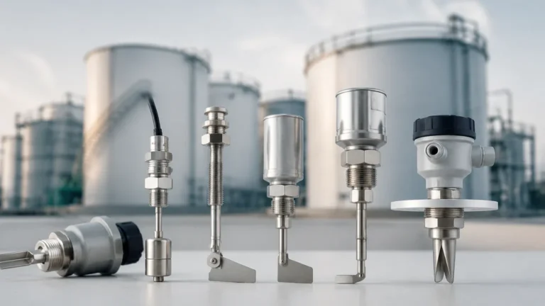
Industrial float level switches are among the most established and reliable technologies for point level detection in liquid storage and processing. These devices operate on the fundamental principle of buoyancy to provide a discrete output signal—typically a dry contact closure—when a liquid reaches a predefined high or low level. In industrial environments, where automation and safety are paramount, these switches serve as critical components for pump control, overfill protection, and low-level alarms.
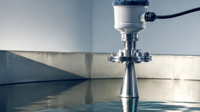
While newer non-contact technologies like radar or ultrasonic sensors have gained popularity, Level Switches based on float mechanisms remain a preferred choice for many engineers due to their simplicity, cost-effectiveness, and independence from the electrical properties of the fluid, such as dielectric constant or conductivity.
Measurement Principles of Float Level Switches
The operation of industrial float level switches is governed by Archimedes' principle, which states that any object, wholly or partially immersed in a fluid, is buoyed up by a force equal to the weight of the fluid displaced by the object. In a level switch application, the float is designed with a density lower than that of the process liquid, ensuring it moves vertically as the liquid level rises or falls.
There are two primary sensing mechanisms used to translate this physical movement into an electrical signal:
1. Magnetic Reed Switch Principle
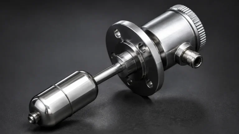
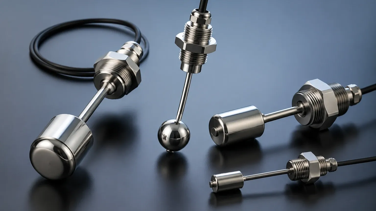
This is the most common design for modern industrial applications. A permanent magnet is sealed inside a hollow float. The float travels along a stationary stem containing one or more hermetically sealed reed switches. As the float approaches a reed switch, the magnetic field causes the overlapping reeds to make contact (closing the circuit) or separate (opening the circuit).
Because the electrical components are isolated within the stem, this design is highly resistant to moisture, oxidation, and corrosion. It also allows for multiple switching points on a single stem, providing high and low alarms within one installation point.
2. Mechanical Microswitch Principle
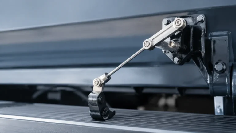
In this design, the float is typically attached to a lever arm or a cable. As the float moves, the mechanical force is transmitted through a pivot or a flexible seal to trigger a microswitch. This type is often found in heavy-duty side-mounted switches or large cable-suspended "bobber" switches used in wastewater sumps. These are capable of switching higher electrical currents directly without the need for an intermediate relay, though they are more susceptible to mechanical wear over time.
Types of Industrial Float Level Switches
Selecting the correct configuration depends on the tank geometry, the available mounting ports, and the specific requirements of the process.
Top-Mounted Single or Multi-Point Switches
These are installed through a flange or threaded NPT/BSP connection at the top of the vessel. A vertical rod extends into the tank. This configuration is ideal for deep tanks where side access is restricted. Multi-point versions can monitor several levels (e.g., Low-Low, Low, High, and High-High) using a single process entry point.
Side-Mounted Horizontal Switches
Installed through the side wall of a tank, these switches use a hinged float that moves in an arc. When the liquid level rises, the float hinges upward, triggering the internal switch. These are compact and excellent for small vessels or for providing redundant high-level alarms in large tanks.
Cable-Suspended Float Switches
Often referred to as "tilt switches," these consist of a weighted float suspended by a flexible chemical-resistant cable. As the liquid rises, the float tilts, causing an internal ball to move and activate a switch. These are primarily used in open sumps, pits, and large water treatment basins where significant turbulence or debris might damage a rigid rod.
Technical Selection Criteria
To ensure the longevity of industrial float level switches, engineers must evaluate several technical parameters beyond just the physical dimensions. Failure to match the switch to the process conditions can lead to premature failure or inaccurate switching.
Specific Gravity (SG)
For a float to function, the liquid must be dense enough to provide sufficient buoyant force. Most industrial floats are designed for liquids with an SG of 0.8 or higher, but specialized floats are available for light hydrocarbons with an SG as low as 0.45. If the liquid density is lower than the float's design limit, the float will sink and the switch will fail to trigger.
Material Compatibility
The choice of material is dictated by the chemical nature of the fluid and the operating temperature. Common materials include:
* Stainless Steel (304 or 316L): The standard for oil, water, and high-pressure applications. It offers excellent temperature resistance (up to 200°C or higher with specialized designs).
* Polypropylene (PP): A cost-effective choice for general acidic or alkaline solutions at lower temperatures.
* PVDF / PTFE: Reserved for highly aggressive chemicals and high-purity applications where metallic contamination must be avoided.
Pressure and Temperature
Hollow floats are susceptible to crushing if the process pressure exceeds their design limit. Standard stainless steel floats can often handle up to 30 bar (approx. 435 psi), while plastic floats are usually limited to 2-5 bar. Similarly, the internal electronics or reed switches have specific temperature thresholds; exceeding these can cause the magnet to lose its field strength or the switch contacts to fuse.
Selection Reference Table
| Feature | Stainless Steel (316L) | Polypropylene (PP) | PVDF / PTFE |
| :— | :— | :— | :— |
| Max Temperature | Up to 250°C | Up to 80°C | Up to 130°C |
| Max Pressure | Up to 40 bar | Up to 3 bar | Up to 6 bar |
| Chemical Resistance | Good (Oils, Fuels, Water) | Excellent (Acids/Bases) | Superior (Strong Oxidizers) |
| Common Application | Oil & Gas, Boilers | Water Treatment | Chemical Processing |
| Relative Cost | Moderate | Low | High |
Installation Considerations
Proper installation is critical to prevent "chatter" (rapid cycling of the switch) and mechanical damage.
1. Avoid Turbulence: Do not install a float switch directly in the path of an incoming fluid stream. The kinetic energy of the liquid can cause the float to bounce or the stem to bend. If turbulence is unavoidable, use a stilling well (a perforated pipe) to shield the float.
2. Orientation: Ensure vertical stems are perfectly plumb. Even a slight tilt can increase friction between the float and the stem, leading to sticking.
3. Clearance: Maintain adequate clearance from tank walls and internal structures like agitators or heating coils. For magnetic switches, ensure no ferromagnetic materials are close enough to interfere with the magnetic field.
4. Wiring and Protection: Use a relay or a PLC input to handle the switching logic. While some industrial float level switches can handle 110/220V AC, using low-voltage DC (e.g., 24V) is safer and extends the life of the reed switch contacts by reducing arcing.
Limitations and Common Risks
While robust, industrial float level switches are not suitable for every application. Engineers should be aware of the following limitations:
* Build-up and Scaling: In liquids that crystallize or contain heavy solids (e.g., wastewater with high grease content), material can build up on the float or stem. This increases the float's weight or causes it to jam. In such cases, non-contact sensors or "clog-free" tilt switches are preferred.
* Viscosity: Highly viscous liquids (like heavy syrups or crude oil at low temperatures) can impede the movement of the float, leading to a delayed response.
* Mechanical Wear: Because these are moving parts, they eventually succumb to mechanical fatigue, especially in applications with frequent level cycles.
* Magnetite Accumulation: In closed-loop heating systems, metallic particles (magnetite) can be attracted to the magnetic float, eventually preventing it from sliding along the stem.
Maintenance and Troubleshooting
Industrial float level switches are generally low-maintenance, but a routine inspection schedule is recommended, particularly in critical safety loops.
* Visual Inspection: Periodically remove the switch to check for signs of corrosion, pitting on the float, or material buildup.
* Manual Actuation: With the system safely bypassed, manually move the float to ensure the control room receives the correct signal. This verifies both the switch integrity and the wiring loop.
* Continuity Testing: Use a multimeter to check the resistance of the switch contacts. A high resistance reading when the switch is closed indicates pitted or fouled contacts, signaling that the unit should be replaced.
Frequently Asked Questions (FAQ)
Q: Can I change a float switch from Normally Open (N.O.) to Normally Closed (N.C.)?
A: For many magnetic reed float switches, yes. This is often achieved by removing a retaining clip, flipping the float 180 degrees, and reinstalling it. However, always consult the manufacturer's documentation, as some designs are factory-set.
Q: What is the difference between a level switch and a level transmitter?
A: A level switch provides a point-specific output (On/Off) at a certain level. A level transmitter provides a continuous signal (e.g., 4-20mA or Modbus) representing the exact level across the entire range of the tank.
Q: Why did my reed switch fail after only a few cycles?
A: The most common cause is "contact welding" due to an inductive load (like a motor or a large solenoid) causing a voltage spike when the switch opens. Always use a protective diode (for DC) or a varistor (for AC), or ideally, use the switch to trigger a high-impedance relay rather than the load itself.
Q: Are float switches suitable for hygienic food and beverage applications?
A: Yes, provided they are constructed from 316L stainless steel with a high-grade surface finish (Ra < 0.8 µm) and use tri-clamp fittings to eliminate crevices where bacteria can grow.
In summary, industrial float level switches remain a cornerstone of process control. By understanding the buoyancy principles, selecting the appropriate materials for the chemical environment, and following strict installation guidelines, facilities can achieve reliable point level detection for years of service. For complex applications involving high pressure or aggressive media, consulting with a specialist to match the specific gravity and pressure ratings is the best path toward operational safety.