Level Switch Hydraulic
Level Switch Hydraulic
In industrial fluid power systems, the hydraulic reservoir serves as the heart of the operation, providing the necessary volume of oil to sustain pressure, dissipate heat, and allow for the settlement of contaminants. Maintaining the correct fluid level within these reservoirs is not merely a matter of operational efficiency; it is a critical safety requirement. A level switch hydraulic assembly provides the necessary point-level detection to prevent pump cavitation, oil overheating, and catastrophic system failure.
Reliable monitoring ensures that hydraulic pumps—often the most expensive components in a circuit—never run dry. This guide explores the engineering principles, selection criteria, and installation requirements for integrating Level Switches into modern hydraulic systems.
Understanding the Role of Level Switches in Hydraulic Systems
Hydraulic systems operate under high-pressure conditions where fluid integrity is paramount. The level switch acts as a sentinel, typically configured to trigger alarms or emergency stops (E-stops) when fluid levels drop below a safe threshold. Conversely, they can also prevent overfilling during maintenance cycles, which could lead to inadequate air space for thermal expansion or foaming.
Unlike general-purpose water level sensors, a level switch hydraulic must be engineered to withstand specific environmental challenges, including high-viscosity oils, rapid temperature fluctuations, and the presence of metallic particulates. Furthermore, the compatibility between the sensor materials and the hydraulic fluid (whether mineral-based, water-glycol, or synthetic esters) is a primary engineering consideration.
Core Measurement Principles for Hydraulic Fluids
To select the correct instrument, engineers must first understand the physics behind different sensing technologies. While many principles exist, four are predominantly used in hydraulic applications.
1. Magnetic Float Principle
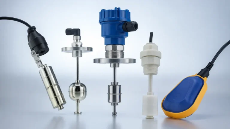
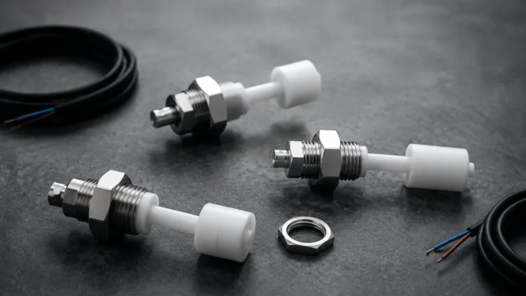
This is the most common technology for hydraulic reservoirs. A float containing a permanent magnet moves vertically along a stem. Inside the stem, a hermetically sealed reed switch is positioned at a specific set point. As the float rises or falls with the oil level, the magnetic field actuates the reed switch (either closing or opening the circuit).
* Advantages: Simple, reliable, and requires no external power to operate the switch itself. It is highly compatible with most mineral oils.
* Limitations: Susceptible to magnetic debris (fine metal shavings) which can cling to the float and cause sticking.
2. Capacitive Level Sensing
Capacitive switches measure the change in electrical capacitance between two electrodes (or one electrode and the tank wall) caused by the presence of the fluid. Since hydraulic oil has a different dielectric constant than air, the switch can accurately detect the interface.
* Advantages: No moving parts, making it resistant to mechanical wear and vibration. It can often be adjusted to ignore foam or film buildup.
* Limitations: Requires calibration based on the specific dielectric constant of the hydraulic fluid used.
3. Optical Level Sensing
Optical switches utilize an infrared LED and a phototransistor housed within a glass or plastic prism. When the sensor tip is in the air, the light reflects internally within the prism back to the receiver. When immersed in oil, the light refracts into the liquid, breaking the circuit.
* Advantages: Extremely compact and provides very fast response times. Ideal for small power packs where space is limited.
* Limitations: Not suitable for fluids that are highly reflective or prone to heavy coating/staining of the prism tip.
4. Ultrasonic Point Level Detection
Ultrasonic switches use high-frequency sound waves. A crystal transducer emits a pulse that travels across a gap in the sensor tip. If the gap is filled with liquid, the pulse reaches the receiver; if filled with air, the signal is attenuated.
* Advantages: Solid-state with no moving parts. Unaffected by the dielectric properties or conductivity of the oil.
* Limitations: Can be affected by heavy aeration or foaming in the hydraulic fluid, which scatters the ultrasonic signal.
Technical Specifications for Level Switch Hydraulic Applications
When specifying a level switch hydraulic for a project, the following technical parameters must be confirmed to ensure longevity and accuracy.
Fluid Compatibility and Seal Materials
Hydraulic fluids vary significantly in chemical composition. Standard NBR (Nitrile) seals are generally sufficient for mineral-based oils. However, if the system uses fire-resistant fluids like phosphate esters (e.g., Skydrol), FKM (Viton) or EPDM seals may be required. Using incompatible materials will lead to seal swelling, leakage, and eventual switch failure.
Pressure and Temperature Ratings
While hydraulic reservoirs are typically vented to the atmosphere (low pressure), the level switch must still handle the operating temperature of the oil, which can range from 40°C to 80°C (104°F to 176°F) in standard systems, and even higher in high-performance machinery. The switch housing and internal components must be rated for at least 20% above the maximum expected system temperature.
Electrical Configuration
Most industrial level switches offer SPST (Single Pole Single Throw) or SPDT (Single Pole Double Throw) contacts. It is standard practice to use "Normally Closed" (NC) contacts for low-level alarms. In this configuration, the circuit remains closed when the oil level is safe; if the level drops or a wire breaks, the circuit opens, triggering a fail-safe alarm.
Installation Best Practices in Industrial Reservoirs
Correct installation is as vital as selecting the right technology. Poorly placed sensors can lead to false positives or delayed responses.
1. Avoid Turbulence Zones: Do not install the level switch directly near the return line or the pump suction inlet. Turbulence and localized fluid velocity can cause float "chatter" or false readings in optical and capacitive sensors.
2. Stilling Wells: In reservoirs with high agitation, a stilling well (a vertical pipe with vent holes) should be used to surround the switch. This provides a calm surface area for the float or sensor tip to interact with.
3. Vertical vs. Horizontal Mounting:
* Top-mount (Vertical): Allows for multiple switch points on a single stem (e.g., High, Low, and Low-Low levels).
* Side-mount (Horizontal): Useful for single-point detection when the top of the tank is obstructed by other components like breathers or manifolds.
4. Clearance: Ensure the float has at least 25 mm (1 inch) of clearance from internal baffles or tank walls to prevent mechanical interference.

Selection Criteria and Comparative Analysis
The following table provides a general comparison of common technologies used in level switch hydraulic applications.
| Technology | Max Pressure (Bar) | Temp Range (°C) | Viscosity Handling | Best Application |
| :— | :— | :— | :— | :— |
| Magnetic Float | Up to 40 | -40 to +120 | Moderate | Standard mineral oil reservoirs |
| Capacitive | Up to 100 | -40 to +150 | High | Non-conductive synthetic oils |
| Optical | Up to 50 | -20 to +100 | Low to Moderate | Compact hydraulic power units (HPUs) |
| Ultrasonic | Up to 20 | -30 to +90 | Moderate | Systems requiring solid-state reliability |
Maintenance, Troubleshooting, and Risk Mitigation
Even the most robust level switch hydraulic requires periodic inspection to ensure system integrity.
Common Risks
* Magnetic Contamination: In systems without adequate magnetic filtration, fine metallic wear particles can accumulate on the magnetic float. This increases the float's mass, causing it to sink lower than intended or stick to the stem. Regular cleaning or the use of "shielded" magnetic floats can mitigate this.
* Aeration and Foaming: If the hydraulic return line is above the oil level, it can create foam. Foam can give false "high" readings to capacitive sensors or cause ultrasonic sensors to lose their signal. Ensuring return lines are submerged and using anti-foaming additives is essential.
* Dielectric Shift: If a capacitive switch is used and the oil type is changed (e.g., switching from mineral to synthetic), the switch must be recalibrated to the new fluid's dielectric constant.
Troubleshooting Steps
1. Continuity Check: Use a multimeter to verify the switch state changes when the float is moved manually (if possible) or when the tank is drained.
2. Visual Inspection: Check for coating on optical prisms or buildup on capacitive probes.
3. Wiring Integrity: Ensure that the IP rating (e.g., IP65 or IP67) of the cable entry is maintained. Moisture ingress is a leading cause of intermittent electrical faults in hydraulic environments.
Frequently Asked Questions
Q: Can I use a standard water level switch for hydraulic oil?
A: Generally, no. Water level switches often use materials like PVC or standard rubber that degrade rapidly when exposed to hydraulic oils. Furthermore, the specific gravity of hydraulic oil (typically 0.85 to 0.92) is lower than water (1.0), meaning a float designed for water may not have enough buoyancy to rise in oil.
Q: How do I prevent "nuisance tripping" caused by machine vibration?
A: For high-vibration environments, solid-state switches (capacitive or optical) are preferred over mechanical float switches. If a float switch must be used, look for models with dampened reed switches or use an electrical time-delay relay in the control panel to ignore momentary level fluctuations.
Q: What is the benefit of a multi-point level switch hydraulic?
A: A multi-point switch allows a single entry point into the tank to provide multiple signals. For example, the first point can trigger a "Maintenance Required" warning, while the second, lower point triggers an automatic system shutdown to prevent pump damage.
Conclusion
Selecting the appropriate level switch hydraulic is a fundamental step in engineering a reliable fluid power system. By understanding the measurement principles—ranging from simple magnetic floats to advanced capacitive sensors—and accounting for the specific chemical and physical properties of the hydraulic fluid, engineers can significantly reduce the risk of downtime.
For more detailed technical data and to explore specific hardware options, engineers are encouraged to Review product options and application support to find the ideal match for their specific industrial requirements. Proper specification today prevents the costly hydraulic failures of tomorrow.