Level Switch Relay
Level Switch Relay
In the landscape of industrial automation, the level switch relay serves as the critical interface between a sensing element and the control machinery. While a level sensor detects the presence or absence of a medium at a specific point, the relay is the component that translates this detection into a functional action—such as starting a pump, opening a valve, or triggering an audible alarm. Understanding the technical synergy between the sensor and the relay is essential for engineers designing reliable liquid or solid level control systems.
Measurement Principles and Sensor Interaction
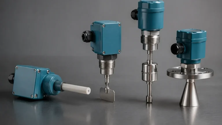
Before selecting a level switch relay, it is necessary to understand the measurement principles of the sensors that provide the input signal. Level Switches operate on various physical principles, each producing a specific output that the relay must interpret.
Float and Magnetic Switches
These rely on buoyancy. A float containing a magnet moves with the liquid level, actuating a reed switch. The output is typically a simple dry contact (volt-free). The relay in this circuit provides the power to drive the load, as reed switches themselves have very low current ratings (often less than 0.5A).
Vibrating Tuning Fork Switches
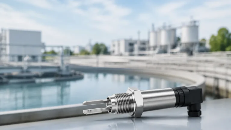
These sensors use piezoelectric crystals to vibrate a fork at its natural frequency. When the fork is submerged in a medium, the frequency changes. The internal electronics detect this shift and signal the relay. These are highly reliable for preventing overfill in turbulent or aerated liquids.
Conductive Level Switches
This principle uses the conductivity of the liquid itself. When the liquid touches an electrode, a low-voltage circuit is completed. The level switch relay in this application is specialized; it must provide a low-voltage AC signal to the probes to prevent electrolysis while monitoring the resistance change to trigger the output.
Capacitive Level Switches
These measure the change in capacitance between an electrode and the vessel wall. They are ideal for solids and non-conductive liquids. The relay associated with these sensors often includes sensitivity adjustments to ignore material buildup on the probe.
The Role of the Relay in Level Control
A level switch relay is more than just a switch; it is a logic controller. In industrial B2B applications, the relay performs three primary functions:
1. Signal Amplification: Most sensors output low-power signals (mA or low-wattage DC). The relay uses this signal to switch high-power AC or DC loads, such as a 2.2 kW pump motor.
2. Electrical Isolation: The relay provides galvanic isolation between the sensing circuit (which may be in contact with hazardous or conductive fluids) and the high-voltage control panel. This protects sensitive PLC (Programmable Logic Controller) inputs from surges.
3. Control Logic (Hysteresis): A single relay can often manage "latched" control. For example, in a "pump down" application, the relay turns the pump on when the high-level switch is triggered and keeps it running until the low-level switch is cleared. This prevents "chattering"—the rapid cycling of the pump due to surface turbulence.
Key Evaluation Criteria for Selection
When specifying a level switch relay, engineers must match the relay's electrical characteristics to both the sensor and the final actuator. Use the following criteria for evaluation:
Contact Rating and Load Type
Determine the maximum current (Amps) and voltage (Volts) the relay contacts must handle. For inductive loads like motors or solenoids, the inrush current can be 5 to 10 times the steady-state current. Ensure the relay is rated for the specific Load Category (e.g., AC-15 for electromagnetic loads or DC-13 for solenoids).
Supply Voltage
Relays are available in various supply configurations. Common industrial standards include 24V DC for modern control cabinets and 110V/230V AC for older infrastructure or standalone pump stations.
Response Time
In high-speed filling lines, a delay of even 500ms can lead to an overflow. Conversely, in tanks with splashing liquids, a built-in time delay (adjustable from 0 to 30 seconds) is preferred to filter out false triggers.
Mounting and Form Factor
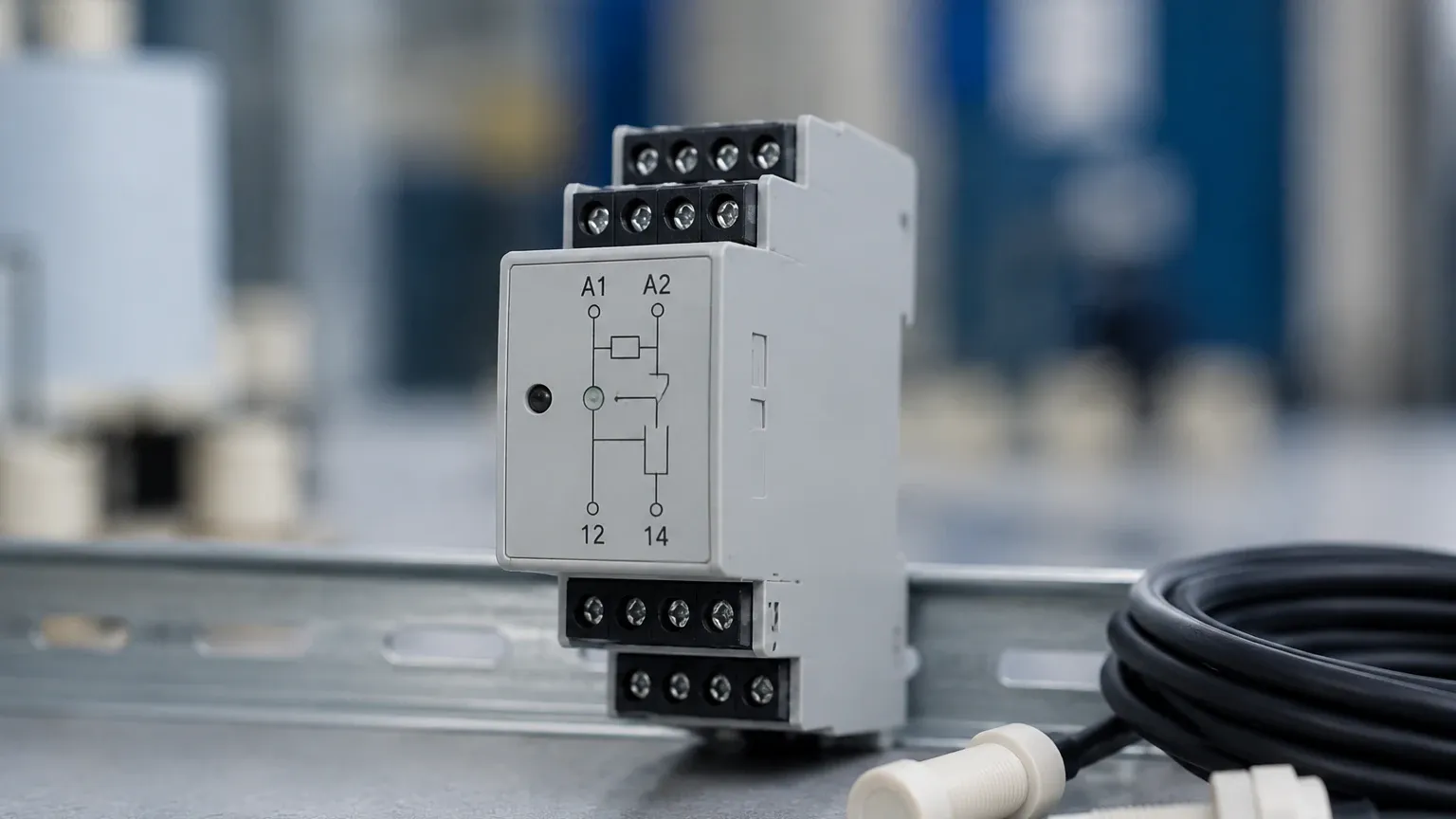
Most industrial level switch relays are designed for 35mm DIN rail mounting within a control cabinet. However, for field-mounted applications, look for relays integrated into NEMA 4X or IP66-rated enclosures.
Practical Selection Table
The following table compares common relay configurations used in industrial level measurement.
| Feature | Electromechanical Relay (EMR) | Solid State Relay (SSR) | Conductive Controller Relay |
| :— | :— | :— | :— |
| Switching Mechanism | Physical moving contacts | Semiconductor (Opto-isolated) | Resistance-sensing circuit |
| Life Expectancy | ~100,000 to 1,000,000 cycles | Virtually unlimited | High |
| Switching Speed | 10ms – 20ms | < 1ms | 50ms – 500ms |
| Heat Dissipation | Negligible | High (Requires heat sinking) | Low |
| Best Use Case | General purpose, high AC loads | High-frequency switching | Conductive liquids (Water/Acid) |
| Failure Mode | Contacts may weld or wear | Usually fails in closed state | Sensitive to probe fouling |
Installation Considerations and Best Practices
Proper installation is vital to ensure the longevity of the level switch relay and the safety of the process.
* Fail-Safe Modes: Always configure the relay for fail-safe operation. In a high-level alarm application, the relay should be energized when the level is low and de-energize (drop out) when the level is high or if power is lost. This ensures that a broken wire or power failure triggers the alarm rather than leaving the system unprotected.
* Arc Suppression: When switching inductive loads (solenoids, contactors) with an electromechanical relay, install an RC snubber circuit (for AC) or a flyback diode (for DC) across the load. This prevents arcing across the relay contacts, which significantly extends the relay's life.
* Wiring Separation: Route sensor input wires (low voltage) away from high-voltage power cables to prevent electromagnetic interference (EMI) from causing false trips.
* Sensitivity Adjustment: For conductive or capacitive relays, calibrate the sensitivity while the tank is empty and again when the probe is covered. This ensures the relay can distinguish between the actual medium and residual moisture or foam.
Common Risks and Limitations
While level switch relays are robust, they are subject to specific industrial risks:
1. Contact Welding: If a relay is used to start a large motor directly without a motor starter or contactor, the inrush current can weld the contacts together, preventing the system from shutting off.
2. Chemical Compatibility: While the relay sits in a cabinet, the sensor connected to it must be compatible with the process media. A failure in the sensor's seal can send process fluid into the conduit, eventually reaching the relay terminals.
3. Minimum Load Requirements: Some high-capacity relays require a "minimum switching load" to keep the contacts clean (wetting current). If you use a high-power relay to signal a low-power PLC input, the contacts may develop oxidation and fail to conduct over time.
Frequently Asked Questions (FAQs)
Q: Can I use a single level switch relay for two different tanks?
A: Only if the relay has multiple independent poles (e.g., DPDT) and the control logic for both tanks is identical. Generally, it is safer and more manageable to use one relay per control loop.
Q: What is the difference between SPDT and DPDT in a level relay?
A: SPDT (Single Pole Double Throw) has one set of changeover contacts. DPDT (Double Pole Double Throw) has two independent sets, allowing you to switch a high-voltage pump and a low-voltage PLC signal simultaneously with one relay.
Q: How do I handle "sloshing" in a tank?
A: Look for a level switch relay with a built-in "ON-delay" or "OFF-delay" timer. This requires the sensor to maintain its state for a set period (e.g., 3 seconds) before the relay toggles, effectively filtering out turbulence.
Q: Is a level switch relay required if I have a PLC?
A: Not strictly required, as the PLC can handle the logic. However, using an interposing relay is still recommended to protect the PLC’s internal circuitry from high-voltage loads and to provide a manual override capability.
Conclusion and Next Steps
The integration of a level switch relay is a fundamental step in building an automated level control system. By matching the relay to the specific measurement principle of your Level Switches, you ensure a system that is both responsive and durable.
Before proceeding with a purchase or installation, project teams should confirm the total load requirements (kW or Amps), the desired fail-safe logic, and the environmental conditions of the installation site. For complex applications involving corrosive chemicals or explosive atmospheres, consulting with a technical specialist ensures that the selected relay and sensor combination meets all necessary safety and regulatory standards.