Level Switch Diagram
Level Switch Diagram
In industrial automation and process control, the accurate detection of liquid or solid levels is critical for preventing tank overflows, protecting pumps from dry running, and maintaining inventory levels. A level switch serves as a point-level measurement device, providing a binary signal (on or off) when a material reaches a specific height. To ensure these devices are integrated correctly into a control system, engineers and technicians rely on a level switch diagram. This documentation typically encompasses wiring schematics, installation layouts, and logic configurations that define how the sensor interacts with the broader industrial environment.
Understanding the nuances of a level switch diagram is essential for avoiding common installation errors that lead to equipment failure or safety hazards. This guide explores the principles of level switching, the various types of diagrams used in the industry, and the technical considerations required for successful implementation.
Principles of Point-Level Measurement
Before analyzing a specific level switch diagram, it is necessary to understand the physical principles that govern how these sensors operate. Different technologies are suited for different media, such as water, corrosive chemicals, oils, or granular solids.
Mechanical Float Switches
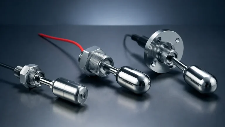
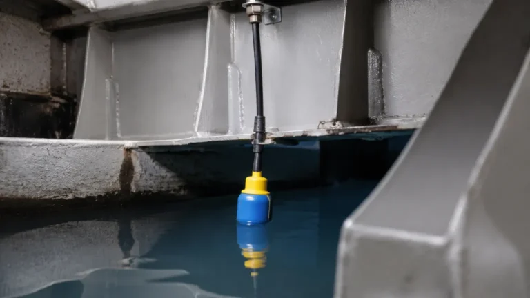
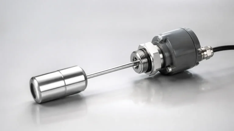
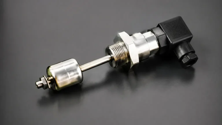
Mechanical float switches operate on the principle of buoyancy. A float containing a magnet moves with the liquid level. When the float reaches a predetermined point, the internal magnet actuates a reed switch or a microswitch. In a wiring diagram, this is represented as a simple contact closure or opening.
Vibrating Fork (Tuning Fork) Switches
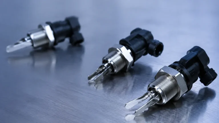
Vibrating fork switches use piezoelectric crystals to vibrate a metal fork at its natural resonance frequency. When the fork is immersed in a liquid or solid, the frequency changes. The electronics detect this shift and trigger the output. These are highly reliable for liquids and powders as they are less affected by turbulence or bubbles.
Capacitive Level Switches
Capacitance switches measure the change in electrical capacitance between a probe and the tank wall (or a ground reference). As the material fills the space, the dielectric constant changes, altering the capacitance. These are often used for non-conductive liquids and solids.
Conductive Level Switches
Used primarily for conductive liquids like water or acids, these switches use electrodes. When the liquid touches the electrode, it completes an electrical circuit between the probe and the tank wall (or another electrode). The level switch diagram for these units often shows multiple probes for high and low-level control.
Interpreting the Level Switch Diagram
A level switch diagram is not a single document but a collection of visual representations that guide different stages of the project lifecycle. These generally fall into three categories: wiring schematics, installation diagrams, and P&ID symbols.
1. Wiring Schematics
The wiring level switch diagram is the most critical for electrical technicians. It illustrates how the sensor is powered and how the output signal is transmitted to a Programmable Logic Controller (PLC) or a relay.
* Two-Wire Configuration: Often used for loop-powered sensors where the power and signal share the same lines.
* Three-Wire Configuration: Common in DC systems (PNP or NPN). One wire for positive power, one for negative, and one for the signal output.
* Relay Output (SPDT/DPDT): Many Level Switches include a dry contact relay. The diagram will show "Common" (COM), "Normally Open" (NO), and "Normally Closed" (NC) terminals.
2. Installation and Mounting Diagrams
These diagrams show the physical placement of the sensor. They specify the required clearance from tank walls, the orientation (vertical vs. horizontal), and the positioning relative to inlet pipes to avoid false triggers caused by splashing or turbulence.
3. P&ID Symbols
In a Piping and Instrumentation Diagram (P&ID), a level switch is represented by a circle containing a code, such as "LSH" (Level Switch High) or "LSL" (Level Switch Low). Lines connecting the circle to the process vessel indicate the physical tapping point.
Technical Selection and Comparison
Choosing the right technology requires matching the sensor's capabilities with the process conditions. The following table summarizes common level switch types and their typical applications.
| Switch Type | Media Type | Pressure Range | Temperature Range | Key Advantage |
| :— | :— | :— | :— | :— |
| Float Switch | Clean Liquids | Up to 40 bar | -40°C to 150°C | Low cost, simple logic |
| Vibrating Fork | Liquids/Solids | Up to 64 bar | -50°C to 250°C | High reliability, no calibration |
| Capacitive | Powders/Liquids | Up to 25 bar | -40°C to 200°C | Adjustable sensitivity |
| Conductive | Conductive Liquids | Atmospheric | -20°C to 100°C | No moving parts, multi-point |
| Optical | Clear Liquids | Up to 50 bar | -30°C to 125°C | Compact size, fast response |
Installation Considerations and Best Practices
When reviewing a level switch diagram for installation, several engineering factors must be addressed to ensure long-term accuracy and reliability.
Orientation and Positioning
* Side Mounting: Often used for high or low-level alarms. The diagram should specify the insertion length to ensure the sensing element is fully immersed when the level reaches the setpoint.
* Top Mounting: Preferred for deep tanks or where side access is restricted. For float switches, stilling wells may be required to prevent the float from swinging in turbulent conditions.
Minimizing Interference
Internal tank structures like ladders, agitators, or heating coils can interfere with the sensor's operation, particularly for capacitive or ultrasonic switches. The installation diagram must define a "clear zone" around the sensor probe. For vibrating forks, the orientation of the tines should be perpendicular to the flow of material to prevent build-up or damage.
Electrical Protection
Industrial environments are prone to electrical noise and surges. The wiring diagram should include specifications for shielded cables and proper grounding. If the switch is installed in a hazardous area (e.g., oil and gas storage), the diagram must reflect the use of intrinsically safe barriers or explosion-proof enclosures.

Common Risks and Failure Modes
Failure to follow the level switch diagram or selecting the wrong technology can lead to several operational risks:
1. Coating and Build-up: In viscous or sticky media, material can accumulate on the sensor. This may cause a "stuck" signal. Vibrating forks and certain capacitive sensors are designed to ignore coating, but mechanical floats will fail in these conditions.
2. Turbulence and Foam: Rapidly moving liquid or thick foam can cause "chattering," where the switch rapidly toggles on and off. This can damage pumps or contactors. Time-delay relays or sensors with built-in damping are recommended.
3. Electrolytic Corrosion: In conductive probe systems, using DC current can cause electrolysis and rapid degradation of the probes. AC sensing currents are standard in modern conductive level switch diagrams to prevent this.
4. Incompatible Materials: The wetted parts of the switch (316 Stainless Steel, PP, PVDF, etc.) must be chemically compatible with the process fluid to prevent leaks or sensor failure.
Project Confirmation Checklist
Before finalizing a purchase or beginning an installation based on a level switch diagram, project engineers should confirm the following technical details:
* Process Connection: Does the thread (BSP/NPT) or flange size match the tank nozzle?
* Supply Voltage: Is the available power 24V DC, 110V AC, or 230V AC?
* Output Type: Does the control system require a relay contact, a transistor output (PNP/NPN), or a NAMUR signal?
* Insertion Length: Is the probe or float arm long enough to reach the desired switching point?
* Environmental Rating: Does the enclosure meet the required IP rating (e.g., IP65, IP67, IP68) for the installation site?
Frequently Asked Questions (FAQ)
Q: Can a level switch be used for continuous level measurement?
A: No. A level switch only detects whether the material has reached a specific point. For continuous tracking (e.g., 0-100% full), a level transmitter (radar, ultrasonic, or hydrostatic) is required.
Q: What is the difference between NO and NC contacts in a wiring diagram?
A: NO (Normally Open) means the circuit is open when the switch is in its "rest" state (usually when the tank is empty). NC (Normally Closed) means the circuit is closed in the rest state. Choosing the correct one is vital for fail-safe logic (e.g., using NC for high-level alarms so that a wire break triggers an alarm).
Q: How do I test a level switch after installation?
A: Most switches have a manual test button or can be tested by manually raising the float or immersing the probe in a sample of the process media. Always ensure the connected pumps or valves are locked out before testing to prevent accidental discharge.
Q: Why does my level switch diagram show a resistor in parallel with the contact?
A: This is often used in "line monitoring" circuits. It allows the PLC to distinguish between a closed switch, an open switch, and a broken wire (open circuit).
By carefully following the technical specifications and the level switch diagram, industrial facilities can ensure precise level control, enhancing both process efficiency and operational safety. For specific product data and wiring configurations, engineers should consult the manufacturer's technical documentation to match the instrument to their unique application requirements.