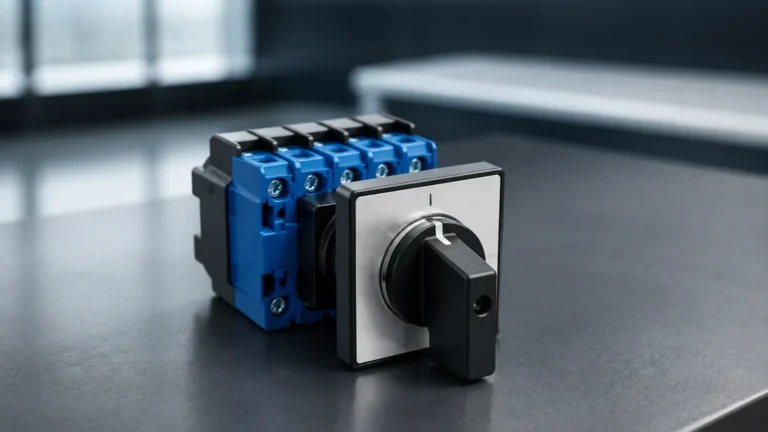
Level 1 Switches
Level 1 Switches
In the hierarchy of industrial automation, "Level 1" represents the sensing and manipulation layer—the fundamental interface where physical process variables are converted into electrical signals. Within this layer, level switches serve as the primary "eyes" of a control system, providing critical point-level detection to prevent tank overflows, protect pumps from dry running, and manage automated filling sequences.
Understanding the mechanics and selection criteria for level 1 switches is essential for process engineers and plant managers who require reliable, binary feedback from their storage vessels and processing tanks. Unlike continuous level transmitters that provide a 4-20mA or digital signal representing the entire range, a level switch triggers a discrete output at a specific, predetermined height.
Principles of Level Switch Measurement
Before selecting a device, it is vital to understand the physical principles that govern different level switch technologies. Each method interacts with the process media differently, making certain types more suitable for specific fluids or environmental conditions.
Float and Magnetic Level Switches
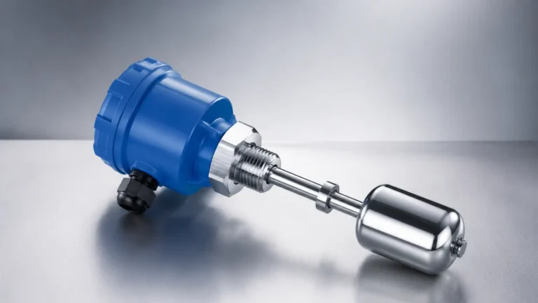
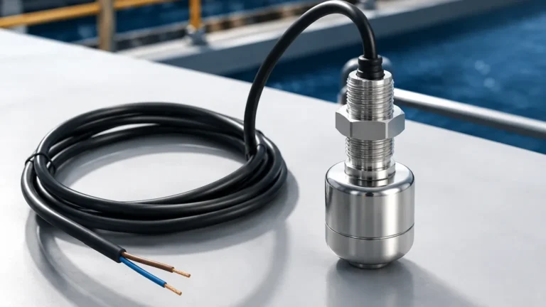
Float switches operate on the principle of buoyancy. A float, containing an internal magnet, moves with the liquid level along a stem. When the float reaches a reed switch embedded in the stem, the magnetic field causes the switch to open or close. These are among the most common level 1 switches due to their simplicity and low cost. They are ideal for clean liquids but can struggle with viscous or scaling fluids that might cause the float to stick.
Vibrating Fork (Tuning Fork) Switches
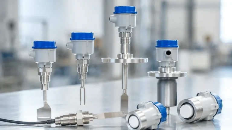
The sensing element of a vibrating fork switch is a pair of tines that vibrate at their natural resonant frequency in air. When the tines are submerged in a liquid or solid, the frequency changes or the vibration is dampened. An electronic circuit detects this shift and triggers the output. These switches are highly versatile, as they are largely unaffected by flow, bubbles, or turbulence.
Capacitance and Admittance Switches
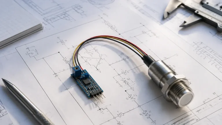
Capacitive switches measure the change in electrical capacitance between the sensor probe and the tank wall (or a reference probe). As the medium rises and replaces the air surrounding the probe, the dielectric constant changes, altering the capacitance. RF Admittance is an advanced version of this technology that uses a driven shield to ignore the effects of material build-up on the probe, making it suitable for sticky or conductive coatings.
Conductivity Level Switches
Used exclusively for conductive liquids (such as water or acids), these switches utilize a low-voltage electrode. When the liquid touches the electrode, it completes an electrical circuit between the probe and the tank wall (or another electrode), triggering the switch. These are extremely robust as they have no moving parts.
Technical Comparison and Selection Criteria
Choosing the right Level Switches requires a detailed analysis of the media properties and the vessel environment. The following table provides a quick reference for common industrial technologies.
| Technology | Media Type | Viscosity Tolerance | Pressure Range | Primary Advantage |
| :— | :— | :— | :— | :— |
| Float | Clean Liquids | Low | Up to 40 bar (580 PSI) | Simple, no power required |
| Vibrating Fork | Liquids/Solids | Medium | Up to 64 bar (928 PSI) | Immune to foam and bubbles |
| Capacitance | Liquids/Granules | High (with Admittance) | Up to 100 bar (1450 PSI) | No moving parts, high temp |
| Conductivity | Conductive Liquids | Low | Up to 25 bar (362 PSI) | Very low cost, robust |
| Rotary Paddle | Bulk Solids | N/A | Atmospheric | Reliable for heavy powders |
Critical Applications for Level 1 Switches
In a B2B industrial context, level 1 switches are rarely used in isolation. They are integrated into larger Safety Instrumented Systems (SIS) or Basic Process Control Systems (BPCS).
1. Overfill Prevention (High-High Alarm): This is perhaps the most critical role for a level switch. If a continuous radar or ultrasonic transmitter fails, the level 1 switch acts as a redundant safety layer to shut down inlet valves before a spill occurs.
2. Pump Dry-Run Protection (Low-Low Alarm): Pumps can be destroyed within minutes if they run dry. A level switch installed near the bottom of a suction tank ensures the pump is interlocked and cannot start unless sufficient head pressure is present.
3. Interface Detection: Specific float or capacitive switches can be calibrated to detect the interface between two immiscible liquids, such as oil and water, allowing for the automated drainage of the heavier phase.
Installation Considerations and Best Practices
The reliability of a level switch is often determined more by its installation than by the device itself. Engineers should adhere to the following guidelines to ensure long-term performance:
Orientation and Positioning
* Horizontal vs. Vertical: Most vibrating fork and capacitive switches can be mounted horizontally through the side of a tank. However, float switches are often mounted vertically from the top. Ensure there is enough clearance for the float or tines to move without hitting internal baffles or agitators.
* Dead Zones: Every switch has a "dead zone" or a minimum distance from the mounting point where it cannot accurately detect the level. Consult the manufacturer's data sheet to ensure the switch is positioned at the correct switching point.
Environmental Factors
* Turbulence: In tanks with high-speed agitators, level switches can be subjected to mechanical stress or false triggers. In these cases, a stilling well (a pipe that surrounds the sensor to dampen liquid movement) should be installed.
* Build-up and Scaling: For applications involving wastewater or cement slurries, sensors with "active shield" or tuning fork designs are preferred over standard capacitance probes to prevent false positives caused by material clinging to the sensor.
Electrical Integration
Level 1 switches typically offer SPDT (Single Pole Double Throw) or DPDT (Double Pole Double Throw) relay outputs. In modern digital plants, PNP/NPN transistor outputs or NAMUR signals (for hazardous areas) are also common. Ensure the voltage rating (e.g., 24V DC or 110/230V AC) matches the control system's I/O cards.

Limitations and Operational Risks
While level switches are indispensable, they are not universal solutions. Users must be aware of specific limitations:
* Moving Parts: Mechanical float switches are susceptible to wear and tear. In high-cycle applications, solid-state sensors like vibrating forks are generally preferred to reduce maintenance costs.
* Media Changes: Capacitive switches are sensitive to changes in the dielectric constant. If a tank is used for different chemicals interchangeably, the switch may require recalibration for each new medium.
* Coating and Bridging: In bulk solids, material can "bridge" over a rotary paddle or coat a probe, indicating a full tank even when it is empty. Selecting a switch with a high-torque motor or vibration-based sensing can mitigate these risks.
Maintenance and Calibration Procedures
For level 1 switches used in safety-critical roles, a regular proof-test interval must be established.
1. Visual Inspection: Check for corrosion on the housing and chemical attack on the wetted parts (e.g., 316L Stainless Steel, PTFE, or PP).
2. Functional Test: If possible, manually raise the liquid level to trigger the switch, or remove the switch and submerge it in a bucket of the process media to verify the relay state changes.
3. Cleaning: For vibrating forks, ensure the space between the tines is clear of debris. For float switches, ensure the float moves freely along the stem without friction.
Frequently Asked Questions (FAQs)
Q: Can level switches be used for continuous level monitoring?
No. Level switches provide point-level detection (on/off). For continuous measurement (0-100%), you should use a radar, ultrasonic, or hydrostatic level transmitter.
Q: What is the difference between a "normally open" (NO) and "normally closed" (NC) configuration?
In an NO configuration, the circuit is open (no current flows) until the level reaches the switch. In an NC configuration, the circuit is closed and opens when the level is detected. For safety-critical applications, NC is often preferred because a broken wire will trigger an alarm (fail-safe).
Q: How do I handle level switching in high-temperature or high-pressure steam applications?
For extreme conditions (e.g., boiler drum level), magnetic level gauges with external switch modules or specialized high-temperature capacitance probes are required. Standard plastic or low-grade stainless steel switches will fail under these stresses.
Q: Are level 1 switches suitable for hazardous (Ex) areas?
Yes, but they must be appropriately certified (e.g., ATEX, IECEx, or UL Class I, Div 1). Intrinsically safe (IS) versions require an isolated barrier in the control cabinet to limit the energy sent to the sensor.
By carefully matching the sensing technology to the physical properties of the media and following rigorous installation standards, level 1 switches provide the robust, reliable feedback necessary for modern industrial process control.