5 Position Switches
5 Position Switches
In industrial process control, monitoring liquid levels is rarely limited to a simple "full" or "empty" state. Complex automation sequences, such as those found in chemical processing, water treatment, and oil storage, often require multiple setpoints to manage pump cycles, trigger safety interlocks, and provide graduated alarms. Multi-point level detection, specifically via 5 position switches, offers a consolidated solution for monitoring five distinct elevations within a single vessel using a single entry point.
These instruments fall under the broader category of Level Switches, designed to provide discrete output signals when a liquid reaches specific heights. By integrating five switching points into a single probe, engineers can reduce the number of tank penetrations, simplify wiring, and lower the overall cost of installation compared to using five individual single-point sensors.
Measurement Principles of Multi-point Level Switches
To understand the application of 5 position switches, it is essential to first examine the underlying technology. While several technologies can achieve multi-point detection, the most common industrial implementation involves magnetic float technology or conductive probes.
Magnetic Float Principle
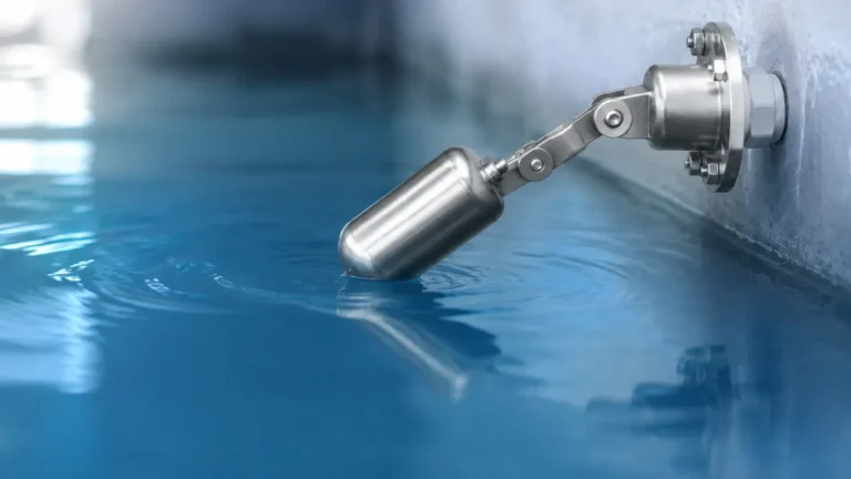
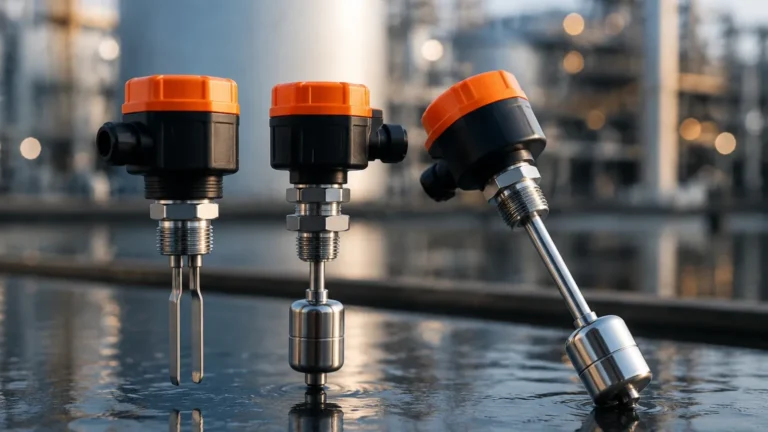
The most prevalent design for a 5 position switch is the magnetic float level transmitter. This instrument consists of a hollow vertical stem containing five stationary reed switches positioned at precise intervals. A buoyant float, containing a permanent magnet, slides up and down the stem as the liquid level changes.
When the float's magnetic field aligns with one of the reed switches, the switch changes state (either closing a normally open circuit or opening a normally closed one). Because the reed switches are hermetically sealed within the stem, they are protected from the process media, ensuring long-term reliability. In a 5-point configuration, the stem is custom-manufactured so that the switches correspond to specific process requirements, such as Low-Low, Low, Intermediate, High, and High-High levels.
Conductivity Principle
For conductive liquids, such as water or acids, multi-electrode conductivity switches are often employed. These units feature five stainless steel or titanium rods of varying lengths. When the liquid touches a rod, an electrical circuit is completed between that rod and a reference electrode (or the tank wall). This technology is valued for its lack of moving parts, making it suitable for applications with minor turbulence or where mechanical floats might jam due to debris.
Ultrasonic and Optical Variations
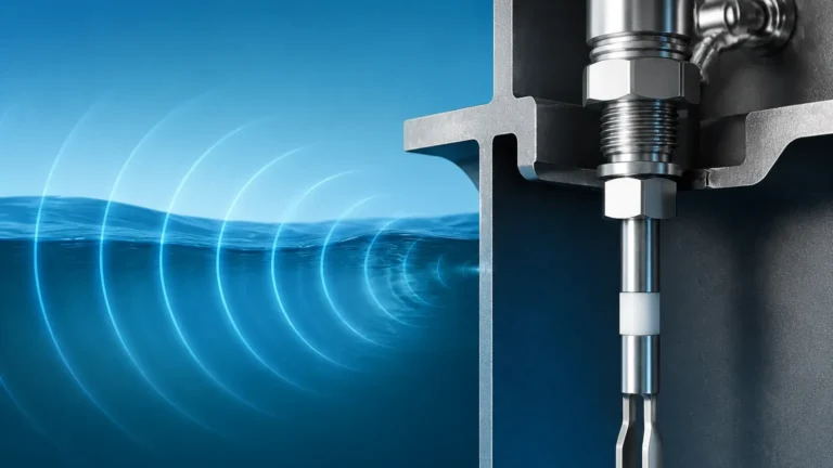
While less common for a single-probe "5 position" configuration, some advanced ultrasonic or optical arrays can be configured to provide five discrete outputs. However, in heavy industrial B2B environments, the magnetic float design remains the standard due to its simplicity, lack of power requirement (for the sensing element itself), and high resistance to pressure and temperature.
Practical Selection Criteria
Selecting the correct 5 position switch requires a detailed understanding of the process media and the physical constraints of the vessel. Engineers must evaluate several mechanical and electrical parameters to ensure the instrument performs accurately over its service life.
1. Material Compatibility
The wetted parts—the stem, the float, and the process connection—must be chemically compatible with the liquid.
- Stainless Steel (304 or 316L): The standard for oil, water, and mild chemicals. It offers high pressure resistance, typically up to 40 bar (approx. 580 psi).
- Plastic (PP, PVC, PVDF): Used for highly corrosive acids or bases where stainless steel would degrade. These are generally limited to lower temperatures, usually below 80°C (176°F).
- Specialty Coatings: PTFE or PFA coatings are used for extremely aggressive media or to prevent material buildup on the probe.
2. Specific Gravity
The float must be lighter than the liquid it is intended to measure. Most industrial floats are designed for a minimum specific gravity (SG) of 0.5 to 0.7. If the liquid is an ultra-light hydrocarbon, a specialized high-buoyancy float is required to ensure the magnet accurately triggers the reed switches.
3. Temperature and Pressure
Standard magnetic level switches can handle temperatures from -20°C to 120°C (-4°F to 248°F). For high-temperature applications, such as boiler feed water or hot oil, specialized high-temperature reed switches and standoff housings are used to protect the wiring from heat. Pressure ratings must also be verified, especially for pressurized storage spheres.
4. Switch Logic and Electrical Interface
Engineers must specify whether each of the five positions should be Normally Open (NO) or Normally Closed (NC) in the "dry" state. Furthermore, the electrical load must be considered. Reed switches typically handle low currents (e.g., 0.5A to 1.0A). If the switch is intended to drive a high-power pump motor directly, an intermediate relay or contactor is mandatory.
Comparison Table: Multi-point Level Switch Technologies
| Feature | Magnetic Float (Reed) | Conductivity Probes | Ultrasonic Array |
| :— | :— | :— | :— |
| Media Type | Clean liquids, oils, chemicals | Conductive liquids (water, acids) | Most liquids, including slurries |
| Moving Parts | Yes (Float) | No | No |
| Max Setpoints | Typically up to 6 or 7 | Up to 5 or 6 rods | Programmable |
| Viscosity Limit | Low to Medium | Low | High |
| Max Temperature | Up to 200°C (Specialized) | Up to 150°C | Up to 100°C |
| Pressure Range | Up to 40 bar | Up to 20 bar | Atmospheric to 5 bar |
Application Engineering and Setpoint Configuration
In a 5 position switch setup, the five points are typically mapped to specific control functions. A common industrial configuration includes:
1. Level 5 (High-High): Emergency overfill alarm and redundant pump shut-off.
2. Level 4 (High): Standard pump stop signal or high-level alert.
3. Level 3 (Mid): Process start/stop or intermediate tank volume notification.
4. Level 2 (Low): Standard pump start signal or low-level alert.
5. Level 1 (Low-Low): Dry-run protection for pumps and critical low-level alarm.
When ordering these instruments, the "L" dimensions (the distance from the mounting flange to each switch point) must be calculated based on the tank's geometry. It is important to account for the "dead zone" at the top and bottom of the probe where the float cannot travel due to the stop collars or the physical thickness of the float itself.
Installation Considerations
Proper installation is critical to the accuracy and longevity of Level Switches. For 5 position switches, which often involve long probes (up to 6000 mm or approx. 20 feet), the following guidelines apply:
* Vertical Alignment: The probe must be installed within 20 degrees of true vertical. Significant tilting can cause the float to bind against the stem, preventing it from following the liquid level.
* Avoid Turbulence: If the tank has an agitator or high-velocity inlet flow, the probe should be installed inside a stilling well (a bypass pipe) to protect the float from mechanical stress and erratic switching.
* Clearance: Ensure there is enough overhead clearance above the tank to insert the long probe during installation. For very tall tanks, sectional probes or flexible stems may be required.
* Magnetic Interference: Keep the switch away from large motors, transformers, or other strong magnetic fields that could inadvertently trigger the internal reed switches.
Limitations and Operating Constraints
While 5 position switches are highly efficient, they are not suitable for every environment.
* Buildup and Scaling: In liquids that crystallize or contain heavy solids, material can build up on the stem or inside the float. This increases friction and may eventually cause the float to stick in one position.
* Interface Measurement: If the tank contains two immiscible liquids (e.g., oil and water), a standard float will sit at the air/liquid interface. Measuring the interface between the two liquids requires a float weighted specifically to sink through the top layer and float on the bottom layer.
* Physical Contact: Because these are contact-based sensors, they are subject to wear and chemical attack. For applications involving ultra-pure chemicals or extremely abrasive slurries, non-contact methods like radar or ultrasonic level meters may be preferred, though they often require more complex integration to provide five discrete switch outputs.
Maintenance and Troubleshooting
Maintenance for 5 position switches is generally minimal. However, periodic inspections should include:
1. Float Mobility: Manually sliding the float along the stem to ensure it moves freely without catching.
2. Continuity Testing: Using a multimeter to verify that each of the five switches opens and closes at the correct physical location.
3. Seal Integrity: Checking the junction box and cable entry points for signs of moisture or corrosion, which could cause short circuits.
If a switch fails to trigger, the most common causes are a punctured float (which has filled with liquid and sunk), magnetic debris clinging to the stem, or a reed switch that has reached the end of its electrical life cycle due to excessive arcing.
Frequently Asked Questions (FAQs)
Q: Can I adjust the switch positions after the probe is installed?
A: In most industrial magnetic float designs, the reed switches are fixed at the factory inside the sealed stem. While some models allow for minor external adjustments, the five positions are typically permanent. It is vital to confirm your dimensions before production.
Q: What is the minimum distance between two switch points?
A: This depends on the size of the float. To prevent magnetic interference between two adjacent reed switches, a minimum separation (usually 50 mm to 75 mm) is required. If points are too close, one float might trigger two switches simultaneously.
Q: Are 5 position switches safe for explosive environments?
A: Yes, provided they are used with an intrinsically safe (IS) barrier or housed in an explosion-proof (Ex d) junction box. Since the reed switches themselves are simple mechanical contacts, they are easily integrated into hazardous area protection schemes.
Q: Can one probe have more than five positions?
A: Yes. Depending on the length of the stem and the size of the float, it is possible to incorporate up to 7 or 8 switching points, though 5 is the standard maximum for most off-the-shelf industrial configurations.
By consolidating five critical level setpoints into a single, robust instrument, 5 position switches provide a reliable and cost-effective solution for multi-stage tank management. Whether used for simple pump control or as part of a comprehensive safety instrumented system (SIS), understanding the mechanical limits and electrical requirements of these devices ensures optimal performance in demanding B2B industrial applications.