Level Switch 3 Wire
Level Switch 3 Wire
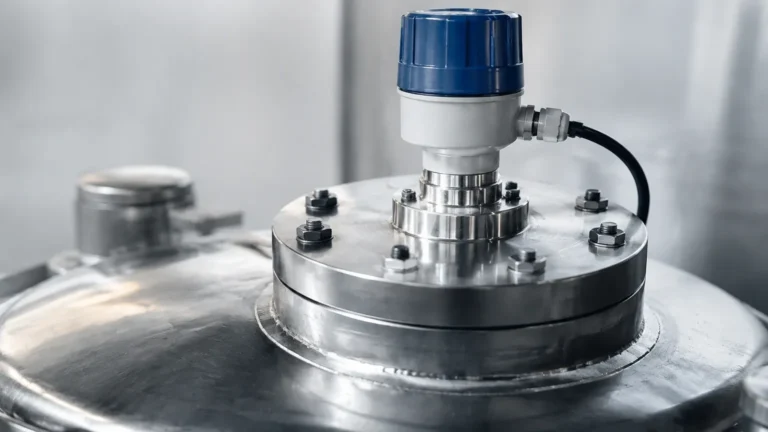
In industrial automation and process control, point level detection is a critical requirement for preventing tank overflows, protecting pumps from dry running, and managing inventory. Among the various electrical configurations available, the level switch 3 wire setup is one of the most common and versatile standards used in modern facilities. This configuration is primarily found in electronic sensors—such as capacitive, ultrasonic, and vibrating fork technologies—where a dedicated power supply is necessary to drive internal microprocessors and high-speed switching components.
Understanding the nuances of 3-wire wiring, specifically the distinction between PNP and NPN outputs and the physical wiring colors, is essential for engineers and maintenance technicians. This guide provides a technical overview of how these devices operate, how to select the right technology, and the best practices for integration into PLC-based control systems.
Measurement Principles of 3-Wire Level Switches
Before selecting a specific Level Switches model, it is important to understand the underlying measurement principles that necessitate a 3-wire configuration. Unlike simple mechanical 2-wire switches that act as a basic "make or break" contact, 3-wire electronic switches require continuous power to operate their sensing elements.
Capacitive Sensing
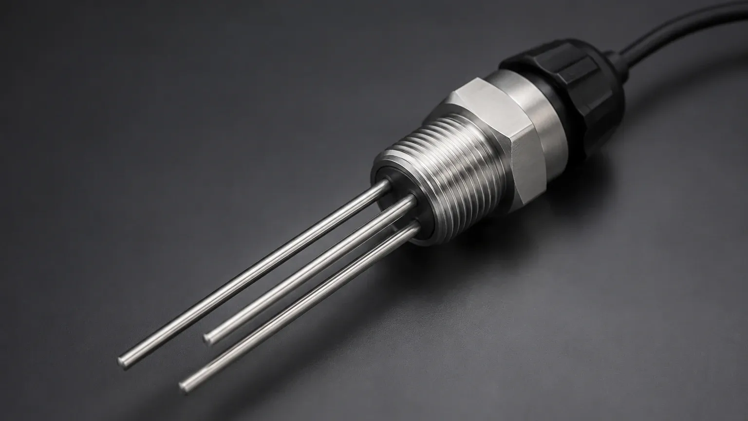
Capacitive level switches measure the change in capacitance between the sensor probe and the tank wall (or a reference electrode). When the medium reaches the probe, the dielectric constant changes, triggering the switch. Because the internal circuitry must constantly monitor this capacitance change and filter out noise, a 3-wire configuration is used to provide stable power (Wire 1 and 2) while sending a clean signal (Wire 3).
Ultrasonic Point Level Detection
Ultrasonic switches use piezoelectric crystals to emit high-frequency sound waves. The sensor detects the presence of a liquid or solid based on the reflection or dampening of these waves. The energy required to pulse the transducer and process the return signal typically requires the higher current stability offered by a 3-wire DC power arrangement.
Vibrating Fork (Tuning Fork)
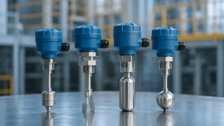
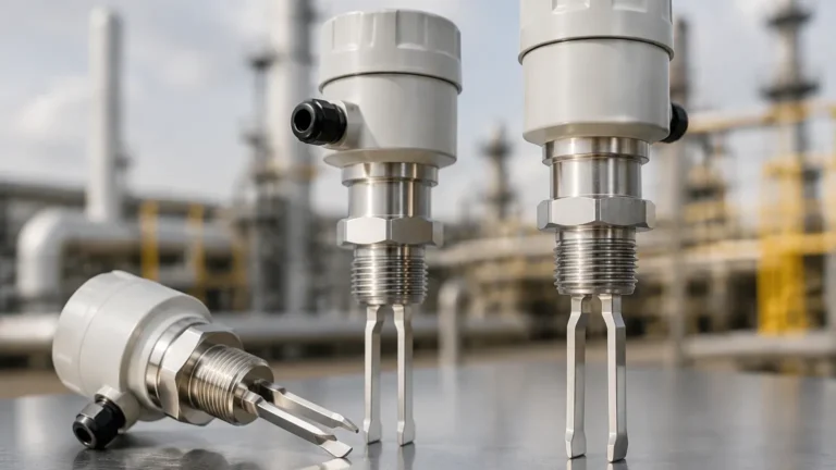
These switches use a fork-shaped element that vibrates at its natural resonant frequency in air. When immersed in a medium, the frequency shifts or the vibration is dampened. An internal electronic circuit detects this shift. In 3-wire DC versions, the electronics are powered independently of the load, ensuring that the switching performance remains consistent regardless of the connected PLC or relay impedance.
The 3-Wire Electrical Configuration
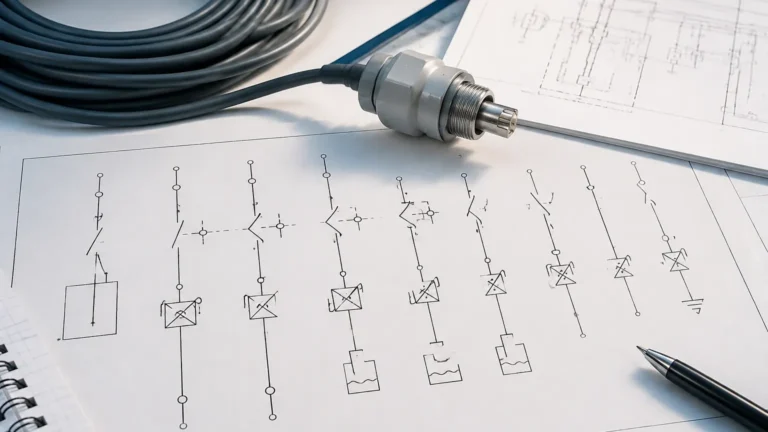
The "3-wire" designation refers to the electrical interface between the sensor and the control system. In a standard DC system (typically 10V to 30V DC), the wires are assigned as follows:
1. Positive Power (V+): Usually color-coded Brown. Connects to the positive terminal of the power supply.
2. Negative Power (0V/GND): Usually color-coded Blue. Connects to the common or ground terminal of the power supply.
3. Switching Output (Signal): Usually color-coded Black. This wire carries the signal to the load (PLC input, relay coil, or lamp).
PNP vs. NPN Logic
When dealing with a level switch 3 wire configuration, the most critical decision is choosing between PNP and NPN logic. This determines how the output wire interacts with the load.
* PNP (Sourcing): The switch connects the output wire to the positive voltage (V+) when triggered. The load must be connected between the Black wire and the Blue (0V) wire. This is the standard in most European and North American industrial systems.
* NPN (Sinking): The switch connects the output wire to the negative voltage (0V) when triggered. The load must be connected between the Black wire and the Brown (V+) wire. This is common in many Asian-manufactured control systems.
Selection Criteria for 3-Wire Level Switches
Selecting the appropriate level switch requires balancing the electrical requirements with the physical properties of the media being measured. Use the following table as a preliminary selection guide for Welk industrial instruments.
| Technology | Typical Media | Max Pressure | Max Temperature | Advantages |
| :— | :— | :— | :— | :— |
| Capacitive | Non-conductive liquids, powders | 25 bar (2.5 MPa) | 120°C | No moving parts; compact size. |
| Ultrasonic | Clean liquids, oils | 3 bar (0.3 MPa) | 80°C | Non-contact; unaffected by density. |
| Vibrating Fork | Slurries, viscous liquids, grains | 40 bar (4.0 MPa) | 150°C | High reliability; ignores foam/bubbles. |
| Optical | Clear liquids, leak detection | 10 bar (1.0 MPa) | 100°C | Extremely small footprint; fast response. |
Key Evaluation Factors
* Supply Voltage: Most 3-wire switches operate on 24V DC. Ensure your power supply can handle the cumulative current draw of all sensors in the loop.
* Load Current: Standard 3-wire solid-state outputs typically support 200mA to 500mA. If you need to drive a large motor or a high-power solenoid directly, an interposing relay is required.
* Switching Frequency: For applications involving fast-filling small containers, check the response time (usually measured in milliseconds).
* Hysteresis: This is the difference between the switch-on point and switch-off point. It prevents "chatter" if the liquid surface is turbulent.
Installation and Wiring Considerations
Proper installation of a level switch 3 wire system ensures long-term reliability and prevents electrical interference. Follow these practical engineering steps:
1. Cable Selection: Use shielded twisted pair cables if the sensor is located more than 50 meters (approx. 164 feet) from the control panel to minimize Electromagnetic Interference (EMI).
2. Conductor Cross-Section: For standard industrial runs, a conductor size of 0.5mm² to 1.5mm² (20 to 16 AWG) is recommended.
3. Mounting Orientation:
* Side Mounting: Ensure the switch is tilted slightly downward (approx. 5-10 degrees) if the media is prone to buildup, allowing droplets to run off the sensing face.
* Top Mounting: Ensure the "dead zone" (the area directly below the sensor where measurement is impossible) is accounted for in the tank's high-level alarm setpoint.
4. Grounding: The sensor housing should be grounded to the tank if the tank is metal, or to a dedicated instrument ground if using plastic tanks, to ensure stable capacitive or electronic readings.
Limitations and Common Risks
While 3-wire switches offer superior performance over 2-wire versions in terms of speed and accuracy, they do have specific limitations:
* Voltage Drop: Although lower than 2-wire switches, there is still a small internal voltage drop (usually <2V). Ensure the remaining voltage meets the minimum high-level threshold of your PLC input card.
* Short Circuit Sensitivity: Solid-state 3-wire outputs are susceptible to damage if the output (Black wire) is accidentally shorted to the power supply (Brown wire) without a load. Many Welk switches include built-in short-circuit protection, but this should always be verified in the datasheet.
* Leakage Current: In the "off" state, a tiny amount of current (residual current) may still flow through the output. While usually negligible (<0.5mA), extremely sensitive high-impedance PLC inputs might occasionally misinterpret this as an "on" signal.
* Polarity Reversal: Connecting the Brown and Blue wires backward can destroy the internal electronics of non-protected sensors. Always use a multimeter to verify polarity before final termination.
Maintenance and Troubleshooting
3-wire switches are generally low-maintenance due to the absence of moving parts in most electronic models. However, periodic checks are recommended:
* Visual Inspection: Check for coating or material buildup on the sensor face. Even "build-up resistant" capacitive switches can fail if a thick crust of conductive material forms.
* LED Indicators: Most modern 3-wire switches feature an integrated LED.
* *Green:* Power is on, sensor is functioning.
* *Yellow/Amber:* Target detected (Output active).
* *Flashing:* Potential fault (short circuit or internal error).
* Multimeter Testing: To test a PNP switch, measure DC voltage between the Black (Output) and Blue (0V) wires. When the switch is triggered, you should read approximately the supply voltage. For an NPN switch, measure between the Black and Brown (V+) wires.
Frequently Asked Questions (FAQs)
Q: Can I use a 3-wire DC switch with an AC power supply?
A: No. Standard 3-wire level switches are designed for DC voltage. Attempting to power them with AC will result in immediate device failure. For AC applications, look for 2-wire AC switches or 5-wire relay output models.
Q: How do I convert a PNP switch to work with an NPN PLC input?
A: The most reliable method is to use a small interface relay. The PNP switch drives the relay coil, and the relay's dry contacts provide the NPN signal to the PLC.
Q: What is the maximum cable length for a 3-wire level switch?
A: This depends on the wire gauge and the current draw of the sensor. Generally, for 24V DC systems using 1.0mm² wire, lengths up to 300 meters (approx. 984 feet) are possible, provided the voltage drop does not fall below the sensor's minimum operating requirement (usually 10V DC).
Q: Does the 3-wire configuration support analog signals (4-20mA)?
A: No. A "switch" provides a discrete (on/off) signal. For continuous level measurement with a 3-wire setup, you would require a level transmitter, not a level switch. However, some advanced Level Switches offer IO-Link capabilities over the third wire, which can provide digital process data.
By following these technical guidelines and selecting a sensor that matches both the chemical compatibility of the media and the electrical logic of the control system, engineers can ensure a robust and maintenance-free level detection solution. For specific wiring diagrams or custom probe lengths, consulting the manufacturer's technical documentation is always recommended during the design phase.