Level Switch 3d
Level Switch 3d
In the modern industrial landscape, the integration of physical hardware with digital design environments is a prerequisite for efficient project execution. For engineers and system integrators, the term "level switch 3d" represents more than just a component; it signifies the necessity of accurate 3D CAD data in the design of complex liquid and solid handling systems. Level switches are critical point-level detection devices used to prevent tank overfills, protect pumps from dry running, and automate filling processes.
Integrating a Level Switches model into a 3D plant layout allows for precise nozzle positioning, interference checking, and maintenance clearance planning. This article provides a technical overview of level switch technologies, selection criteria, and the practical application of 3D modeling in industrial instrumentation.
Measurement Principles of Level Switches
Before selecting a specific model or downloading a level switch 3d file for a project, it is essential to understand the underlying measurement principles. Different technologies are suited to specific media properties such as density, viscosity, and conductivity.
1. Float Level Switches
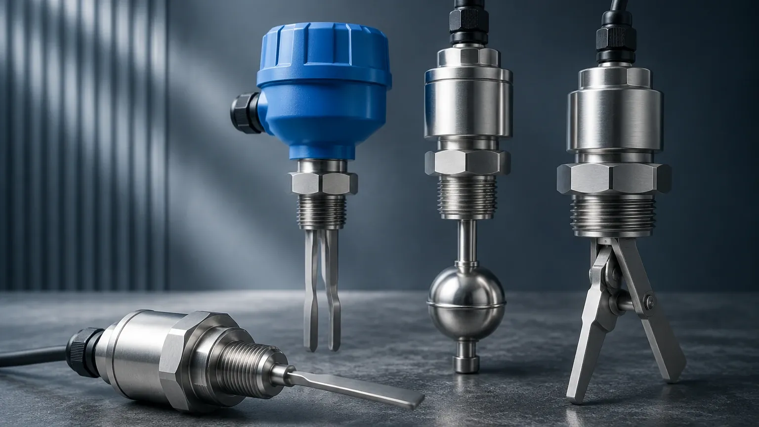
Float switches operate on the principle of buoyancy. A float containing a magnet moves with the liquid level. When the float reaches a predetermined point, the magnetic field triggers a reed switch or a microswitch.
* Application: Best for clean, non-coating liquids.
* Pros: Simple, cost-effective, and requires no power (for reed-type).
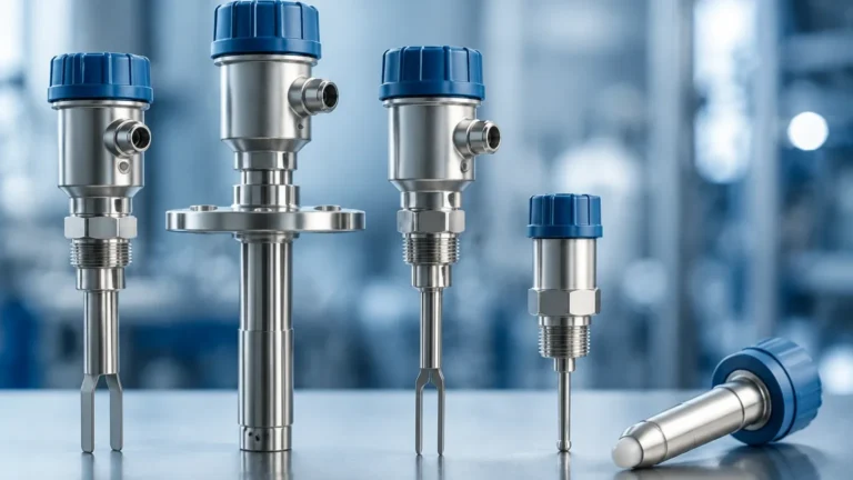
2. Tuning Fork (Vibrating) Level Switches
The sensor consists of two tines that vibrate at their natural resonant frequency in air. When the tines are covered by a liquid or solid, the frequency changes. This shift is detected by the internal electronics and converted into a switching signal.
* Application: Versatile for liquids, powders, and granulates.
* Pros: Immune to bubbles, foam, and vibration; high reliability.
3. Capacitive Level Switches
These sensors measure the change in capacitance between the probe and the tank wall (or a reference probe). As the medium displaces air, the dielectric constant changes, altering the capacitance and triggering the switch.
* Application: Often used for powders, liquids, and interface detection.
* Pros: No moving parts; can be used in high-temperature environments.
4. Rotary Paddle Level Switches
A motor drives a paddle at a low speed. When material reaches the paddle, the rotation is impeded, which triggers a switch and cuts power to the motor.
* Application: Exclusively for bulk solids and powders.
* Pros: Robust and easy to visually verify operation.
5. Ultrasonic Level Switches
These use ultrasonic transducers to detect the presence of a medium. In a gap-type ultrasonic switch, the signal is transmitted across a gap only when liquid is present to conduct the sound waves.
* Application: High-viscosity liquids or chemically aggressive media.
* Pros: Non-contact options available; no moving parts.
The Role of Level Switch 3D Models in Engineering
In contemporary B2B procurement, providing a "level switch 3d" CAD file (typically in STEP, IGES, or Parasolid formats) is a standard requirement for manufacturers like Welk. These models are used in several stages of the engineering lifecycle:
Spatial Coordination and Interference Checking
In crowded industrial environments, such as skid-mounted chemical dosing systems or offshore platforms, space is at a premium. A 3D model allows designers to ensure that the level switch does not collide with internal tank baffles, agitators, or adjacent piping. Using accurate dimensions prevents costly field modifications.
Nozzle and Flange Alignment
Level switches are often mounted via threaded connections or flanges. A 3D model ensures that the nozzle height on the vessel is appropriate for the switch's insertion length. For side-mounted switches, the 3D layout helps confirm that the switch will clear the insulation thickness of the tank.
Digital Twins and Maintenance Planning
As industries move toward digital twins, having a 3D representation of every instrument allows maintenance teams to visualize the plant remotely. It also assists in planning for tool clearance—ensuring that a technician has enough room to unscrew the housing cover or disconnect the cabling.
Technical Selection Criteria
Choosing the correct level switch requires an evaluation of both the process conditions and the physical constraints of the installation. The following table provides a comparison of common technologies.
| Technology | Suitable Media | Max Pressure (approx.) | Max Temp (approx.) | Key Limitation |
| :— | :— | :— | :— | :— |
| Float | Clean Liquids | 30 bar (435 psi) | 150°C (302°F) | Moving parts can jam |
| Tuning Fork | Liquids/Solids | 64 bar (928 psi) | 150°C (302°F) | Material build-up between tines |
| Capacitive | Liquids/Solids | 25 bar (362 psi) | 200°C (392°F) | Sensitivity to dielectric changes |
| Rotary Paddle | Bulk Solids | Atmospheric | 80°C (176°F) | Mechanical wear over time |
| Ultrasonic | Liquids | 10 bar (145 psi) | 100°C (212°F) | Affected by heavy foam/vapor |
Installation Considerations
Correct installation is as vital as selecting the right technology. When reviewing your level switch 3d layout, consider the following factors:
1. Insertion Length: For top-mounted switches, the insertion length must be precisely calculated to reach the desired switching point. In 3D modeling, this is often represented as the distance from the process connection face to the center of the sensing element.
2. Orientation: While tuning fork switches can often be mounted in any orientation, float switches are usually restricted to vertical or horizontal mounting depending on the design. Ensure the 3D model is oriented correctly in the CAD assembly.
3. Flow and Turbulence: If the tank has an inlet near the switch, the flow might cause false triggering or mechanical damage. Use a stilling well or a baffle if the 3D simulation shows high-velocity zones near the sensor.
4. Cable Entry: Always install the switch so that the cable entries point downward to prevent moisture from entering the housing via the conduit. This "drip loop" should be accounted for in the 3D routing of the electrical system.
5. Dead Zones: Some technologies, particularly ultrasonic and radar-based switches, have a "dead zone" or "blocking distance" near the sensor face where measurements are not possible. Ensure the 3D design accounts for this gap.
Limitations and Common Risks
While level switches are robust, certain conditions can lead to failure or inaccurate switching:
* Coating and Build-up: In sticky or viscous media, material can accumulate on the sensor (e.g., the tines of a tuning fork). While some modern electronics can compensate for light coating, heavy build-up will eventually cause a permanent "covered" signal.
* Turbulence and Foam: Surface agitation can cause "chatter" in float and ultrasonic switches. For these applications, a time-delay relay or a tuning fork switch (which is less affected by foam) is recommended.
* Material Density: Float switches rely on the density of the liquid being higher than the float's density. If the process fluid changes (e.g., switching from water to a light oil), the float may no longer function.
* Electromagnetic Interference (EMI): Electronic switches (capacitive, ultrasonic) must be properly shielded and grounded, especially in environments with large motors or variable frequency drives (VFDs).
Frequently Asked Questions (FAQ)
Q: Can I use a liquid level switch for dry bulk solids?
A: Generally, no. Float switches and most ultrasonic gap switches are designed specifically for liquids. For solids, a tuning fork (specifically designed for solids) or a rotary paddle switch is required.
Q: What file formats are usually provided for a level switch 3d model?
A: Most manufacturers provide .STEP or .STP files, as these are neutral formats compatible with SolidWorks, AutoCAD, Rhino, and Catia. Some may also offer .IPT (Inventor) or .SLDPRT (SolidWorks) files.
Q: How do I handle high-pressure applications?
A: For high-pressure vessels, ensure the switch has the appropriate flange rating (e.g., ANSI 150/300 or PN16/40). Hydrostatic or magnetic level switches are often better suited for extreme pressures than simple plastic float switches.
Q: Is it possible to test a level switch without filling the tank?
A: Yes, most modern tuning fork and capacitive switches feature a test magnet or a local test button that simulates a covered state for loop testing and safety checks.
Conclusion
Integrating the right Level Switches into your industrial process requires a balance of physical engineering and digital planning. By utilizing a level switch 3d model during the design phase, engineers can mitigate risks associated with installation errors and spatial constraints. Whether you are managing water treatment, chemical processing, or food production, understanding the measurement principles and limitations of each technology ensures a reliable and safe level control solution. For specific projects, always consult the manufacturer’s technical data sheets and 3D files to confirm compatibility with your process environment.