Level Switch 3d Model
Level Switch 3d Model
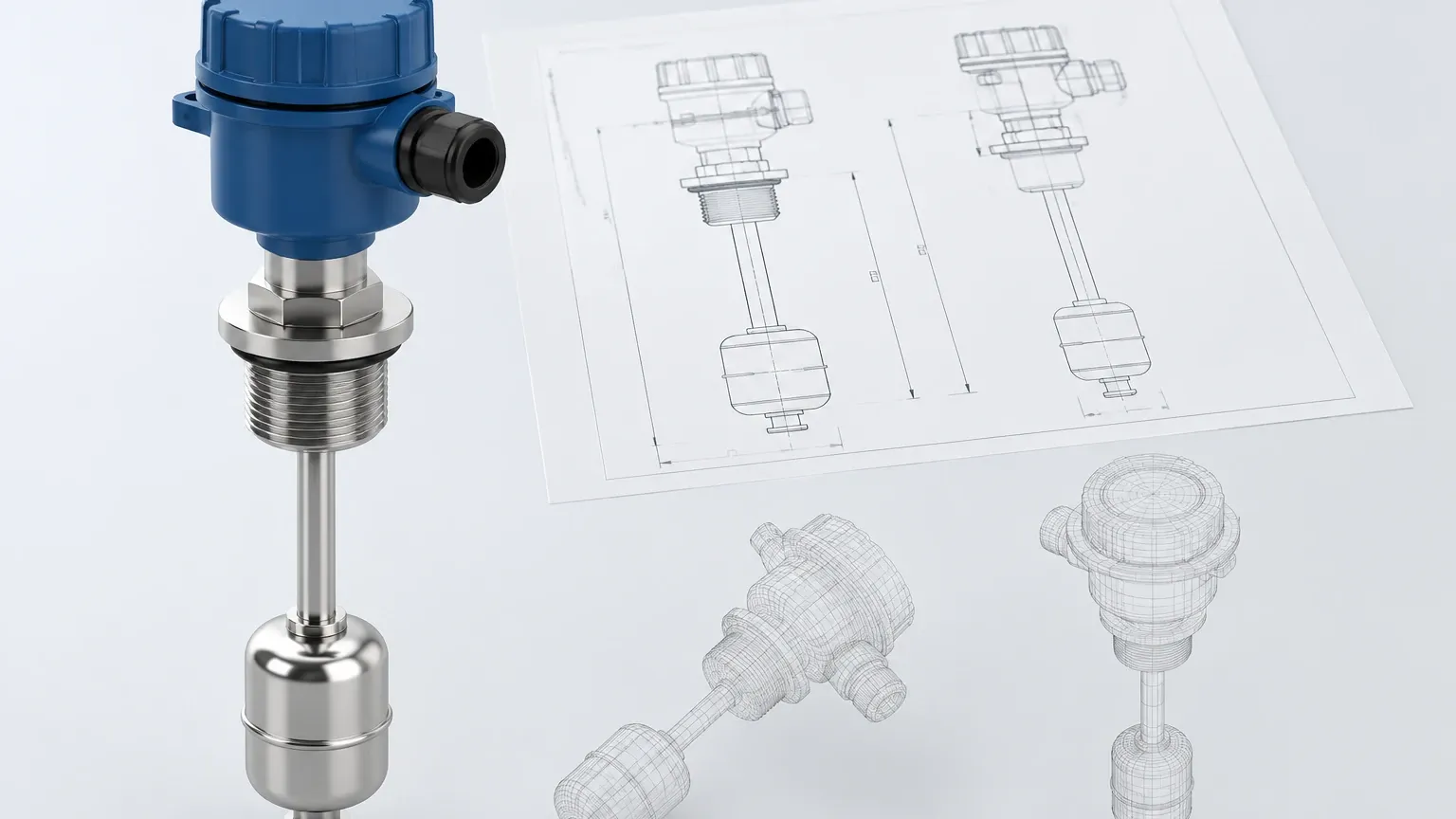
In the field of industrial process control, the integration of hardware components into complex plant designs requires more than just functional specifications. For mechanical and piping engineers, a level switch 3d model is an essential digital asset that ensures spatial compatibility, prevents physical interference, and streamlines the installation of critical instrumentation. As automated systems become more compact and sophisticated, the ability to accurately simulate the placement of Level Switches within a tank or vessel has become a standard requirement in the procurement and design phase.
This article explores the technical principles of various level switch technologies, the importance of utilizing 3D CAD data in engineering projects, and the practical considerations for selecting and installing these devices in industrial environments.
Understanding Level Switch Measurement Principles
Before integrating a level switch into a digital or physical system, it is vital to understand how different technologies interact with the process medium. Level switches are point-level sensors designed to detect the presence or absence of a material at a specific height. Unlike continuous level transmitters, they provide a discrete output (on/off) used for alarms, pump control, or spill prevention.
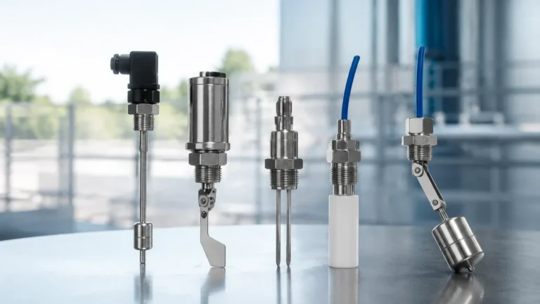
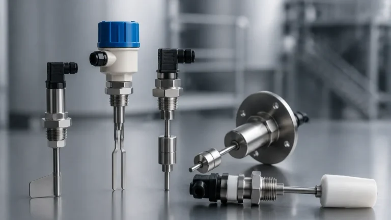
1. Float Level Switches
Float switches operate on the principle of buoyancy. A float containing a permanent magnet moves with the liquid level. When the float reaches a predetermined point, the magnetic field actuates a hermetically sealed reed switch located within the stem.
* Application: Best for clean liquids and simple high/low-level detection.
* 3D Modeling Note: When using a level switch 3d model for a float switch, engineers must account for the "swing radius" or the vertical travel path of the float to ensure it does not strike internal tank baffles or heating coils.
2. Vibrating Tuning Fork Level Switches
The sensing element consists of two tines (the fork) that are vibrated at their resonant frequency by a piezoelectric crystal. When the tines are submerged in a liquid or solid, the frequency of vibration changes. The electronics detect this shift and trigger the output.
* Application: Highly versatile; suitable for liquids, powders, and granulates. They are largely unaffected by flow, turbulence, or bubbles.
* 3D Modeling Note: The insertion length is critical here to ensure the fork is fully immersed in the medium while remaining clear of any agitator blades.
3. Capacitance Level Switches
These sensors measure the change in electrical capacitance between the probe and the vessel wall (or a reference electrode). As the medium displaces air around the probe, the dielectric constant changes, altering the capacitance.
* Application: Effective for both liquids and solids, especially in high-temperature or high-pressure environments.
* Limitation: Can be sensitive to material buildup on the probe, though modern "active shield" designs mitigate this.
4. Rotary Paddle Level Switches
Designed specifically for bulk solids, a low-speed motor rotates a paddle. When the material reaches the paddle, it creates mechanical resistance (torque), which triggers a microswitch and stops the motor.
* Application: Silos containing grain, plastic pellets, or cement.
* 3D Modeling Note: The 3D model must include the full length of the shaft and the paddle diameter to ensure it fits through the mounting nozzle.
The Role of 3D Models in Industrial Engineering
In modern BIM (Building Information Modeling) and Plant 3D workflows, the use of a level switch 3d model allows engineering teams to perform "clash detection." This process identifies if a sensor’s housing, conduit entry, or internal probe will collide with other equipment such as pipes, ladders, or structural beams.
Benefits of High-Fidelity CAD Data
1. Accurate Spacing: Ensures there is sufficient clearance for maintenance personnel to unscrew the housing cover or replace the electronics module.
2. Wiring Path Planning: Allows electrical engineers to visualize the orientation of the cable glands (typically M20 x 1.5 or 1/2" NPT) to plan conduit runs without sharp bends.
3. Nozzle Design: Helps in determining the correct nozzle height and diameter on the vessel to prevent the sensor from being recessed too far, which can cause false readings in viscous liquids.
Technical Selection Criteria
Choosing the right level switch involves balancing process conditions with mechanical constraints. The following table provides a comparison of common technologies used in industrial automation.
Level Switch Technology Comparison Table
| Technology | Suitable Media | Max Temp (Approx.) | Max Pressure (Approx.) | Key Advantage |
| :— | :— | :— | :— | :— |
| Float | Clean Liquids | 150°C (302°F) | 40 bar (580 psi) | Low cost, no power required |
| Tuning Fork | Liquids/Solids | 150°C (302°F) | 64 bar (928 psi) | Maintenance-free, versatile |
| Capacitance | Liquids/Slurries | 250°C (482°F) | 100 bar (1450 psi) | High temp/pressure resistance |
| Rotary Paddle | Bulk Solids | 80°C (176°F) | Atmospheric | Robust for heavy solids |
| Optical | Clear Liquids | 125°C (257°F) | 50 bar (725 psi) | Extremely compact size |
Installation Considerations and Best Practices
When transitioning from a level switch 3d model to physical installation, several factors must be verified to ensure long-term reliability.
Mounting Orientation
* Top Mounting: Standard for float switches and long-probe capacitance switches. Ensure the probe is perfectly vertical to prevent mechanical stress.
* Side Mounting: Common for tuning forks and rotary paddles. For solids, the switch should be mounted at an angle or protected by a baffle if the material fall-path is directly above the sensor.
Turbulence and Agitation
In tanks with agitators, the lateral force of the moving liquid can bend or break long sensor probes. If the 3D model shows the sensor in a high-velocity zone, consider using a stilling well or a shorter, more rugged tuning fork model.
Environmental Protection
For outdoor installations or wash-down areas (common in food and beverage), the housing must meet IP65, IP67, or IP68 standards. The 3D model should accurately represent the housing size, as explosion-proof (Ex d) housings are significantly bulkier than standard plastic or aluminum versions.
Limitations and Common Risks
While level switches are robust, they are not universal solutions. Engineers should be aware of the following risks:
1. Coating and Buoyancy: In float switches, if the liquid is highly viscous or prone to crystallization, the float may stick to the stem, leading to a failure to switch.
2. Dielectric Constant: Capacitance switches require a minimum difference in dielectric constant between the air and the medium. If the medium's properties change (e.g., switching from oil to water), the switch may require recalibration.
3. Mechanical Wear: Rotary paddles have moving parts. Over time, the motor or the shaft seal may wear out, especially in abrasive environments like sand or gravel.
4. Model Inaccuracy: Using a generic level switch 3d model that does not match the specific manufacturer's dimensions can lead to significant errors during the construction phase. Always use the manufacturer-provided STEP or IGES files.
Frequently Asked Questions (FAQ)
Q: What file formats are most common for a level switch 3d model?
A: Most industrial manufacturers provide files in STEP (.stp), IGES (.igs), or Parasolid (.x_t) formats, as these are vendor-neutral and can be imported into AutoCAD, SolidWorks, Revit, and Aveva E3D.
Q: Can a level switch be used for continuous level measurement?
A: No. A level switch only detects a specific point. For continuous tracking (0-100%), you would require a radar, ultrasonic, or hydrostatic level transmitter.
Q: How do I prevent false triggering in foaming liquids?
A: Tuning fork switches are generally resistant to foam, but for heavy foam, a capacitance switch with sensitivity adjustment or a specialized ultrasonic switch may be more appropriate.
Q: Is it necessary to ground a level switch?
A: Yes, especially for capacitance switches and any switch installed in hazardous (Ex) areas. Proper grounding ensures signal integrity and safety.
Conclusion
Integrating Level Switches into an industrial process is a multi-step journey that begins with selecting the right measurement principle and continues through rigorous digital simulation. A high-quality level switch 3d model is more than just a visual aid; it is a critical engineering tool that helps avoid costly field modifications and ensures that the final installation is both functional and maintainable.
By considering factors such as medium properties, pressure ratings, and physical clearances during the design phase, engineers can implement reliable level control solutions that stand up to the rigors of industrial automation. For specific projects, always consult the manufacturer’s technical data sheets and CAD library to ensure the chosen instrument meets the exact requirements of the application.