Vega Guided Wave Radar
Vega Guided Wave Radar
In the landscape of industrial process control, guided wave radar (GWR) has emerged as one of the most reliable methods for continuous level and interface measurement. Among the leading technologies in this field, Vega guided wave radar systems—specifically the VEGAFLEX series—are frequently specified for their ability to handle complex process conditions that often defeat non-contact sensors. This article provides a comprehensive engineering reference for understanding GWR principles, selecting the appropriate probe configurations, and navigating the installation requirements necessary for successful deployment.
Understanding the Measurement Principle: Time Domain Reflectometry (TDR)
Guided wave radar operates on the principle of Time Domain Reflectometry (TDR). Unlike non-contact radar, which broadcasts microwaves through the air, GWR utilizes a physical probe to guide high-frequency, low-energy microwave pulses from the sensor head to the product surface.
The Pulse Journey
When the microwave pulse is emitted, it travels along the length of the probe (the wave guide) at the speed of light. When this pulse reaches the surface of the medium being measured, a portion of the microwave energy is reflected back toward the sensor. This reflection occurs due to the change in the dielectric constant ($\\varepsilon_r$) between the upper medium (usually air or gas) and the process material.
Calculating Distance
The sensor’s electronics measure the time of flight—the interval between the emission of the pulse and the reception of the echo. The distance to the product surface is calculated using the formula:
$$D = \frac{c \times t}{2}$$
Where:
* D is the distance to the surface.
* c is the speed of light (adjusted for the medium through which the pulse travels).
* t is the measured transit time.
Because the pulses are physically guided, the signal is less susceptible to attenuation caused by tank obstructions, foam, or turbulent surfaces. For a broader look at how these technologies integrate into wider industrial automation frameworks, engineers can consult the Main Page for comparative data on various level measurement instruments.
Key Components of Vega Guided Wave Radar Systems
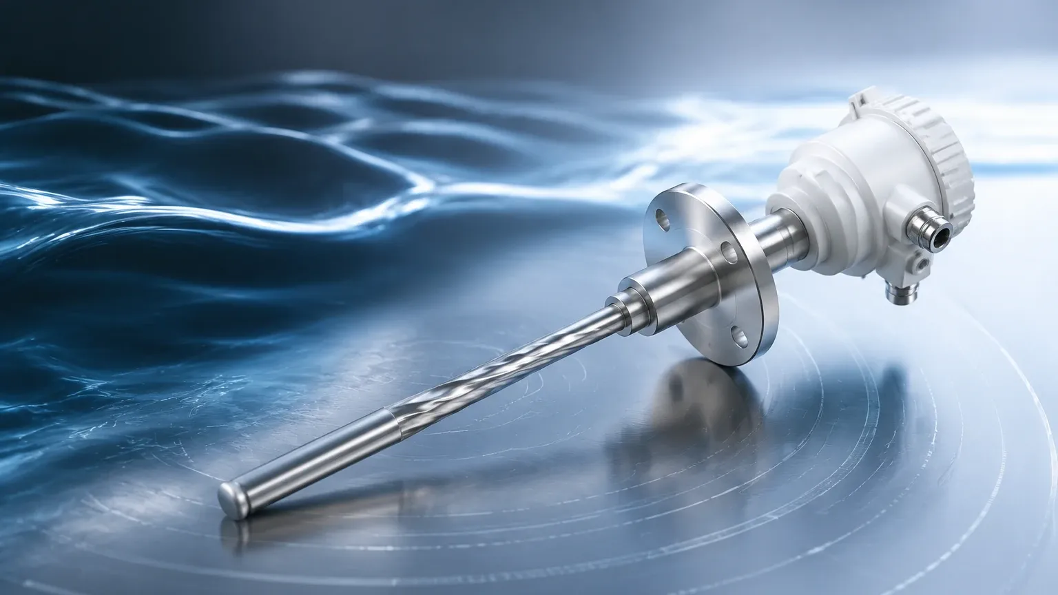
Vega’s GWR portfolio is primarily centered on the VEGAFLEX series. Each model is engineered for specific environmental challenges, categorized by the physical state of the medium and the intensity of the process conditions.
1. VEGAFLEX 81: Designed for liquids. It is a versatile sensor used in standard applications such as water storage, oil tanks, and chemical processing.
2. VEGAFLEX 82: Optimized for bulk solids. It features heavy-duty cable probes designed to withstand the high tensile loads found in silos containing grain, plastic pellets, or minerals.
3. VEGAFLEX 83: Tailored for aggressive liquids or applications with strict hygiene requirements (e.g., food and beverage or pharmaceuticals). It often features PFA-coated probes for chemical resistance.
4. VEGAFLEX 86: Engineered for extreme temperatures and high pressures, making it suitable for steam boiler level control or high-pressure distillation columns.
Selection Criteria: Choosing the Right Probe
The performance of a Vega guided wave radar system is heavily dependent on the probe geometry. Selecting the wrong probe can lead to signal loss or maintenance headaches.
Practical Selection Table
| Probe Type | Application Suitability | Max Range (Approx.) | Pros | Cons |
| :— | :— | :— | :— | :— |
| Single Rod | Standard liquids, viscous media | 6 m | Easy to clean; resists build-up | Sensitive to tank internals; requires larger nozzle |
| Single Cable | Tall silos, bulk solids, liquids | 75 m | Long range; easy transport | Susceptible to swinging; requires bottom anchoring in solids |
| Coaxial | Low dielectric liquids, bypass pipes | 6 m | Highest signal-to-noise ratio; immune to tank internals | Prone to clogging with viscous or dirty liquids |
| Double Rod/Cable | Low dielectric liquids in large tanks | 60 m | Better signal than single rod | Difficult to clean; prone to bridging between probes |
Dielectric Constant ($\\varepsilon_r$) Considerations
The dielectric constant of the medium is the most critical factor in GWR performance. Materials with a high dielectric constant (e.g., water, $\\varepsilon_r \\approx 80$) produce very strong reflections. Materials with low dielectric constants (e.g., hydrocarbons, $\\varepsilon_r < 2$) produce weak reflections. In cases where the $\\varepsilon_r$ is extremely low, a coaxial probe or a bypass pipe is recommended to concentrate the microwave energy and ensure a reliable return signal.
Interface Measurement Capabilities
One of the primary advantages of Vega guided wave radar is its ability to measure both the total level and the interface level between two liquids (e.g., oil over water).
For interface measurement to be successful, the upper medium must have a lower dielectric constant than the lower medium. The microwave pulse passes through the upper layer (which must be non-conductive) and reflects off the interface of the second layer. To ensure accuracy, the upper layer must be at least 50 mm to 100 mm thick, depending on the sensor configuration.
Installation Guidelines and Best Practices
While GWR is more forgiving than non-contact radar, proper installation is essential to prevent false echoes and ensure long-term reliability.
1. Nozzle Geometry
The nozzle diameter and height can impact the signal, particularly in the "dead band" (the area near the top of the probe where measurement is not possible).
* Rod Probes: Ensure the probe is at least 50 mm to 100 mm away from the nozzle wall.
* Cable Probes: Ensure the nozzle is wide enough to prevent the cable from touching the sides during filling or emptying.
2. Proximity to Tank Walls and Obstructions
For single-probe systems, a minimum distance from the tank wall must be maintained (typically 300 mm or more depending on the tank height). If the probe is installed too close to a metal wall or a ladder, the sensor may detect the obstruction instead of the product surface.
3. Avoiding Bridging and Build-up
In applications involving bulk solids or viscous liquids, material can bridge between the probe and the tank wall or between the elements of a double-rod probe. If build-up is expected, a single rod probe with a smooth surface or a PFA coating is the preferred choice.
4. Anchoring Cable Probes
In tall silos, cable probes should be anchored to the bottom if there is significant agitation or if the silo is very deep. However, the anchor must be designed to allow for thermal expansion and the mechanical tension exerted by the product.
Limitations and Operational Constraints
Despite its robustness, Vega guided wave radar has specific limitations that engineers must account for during the design phase:
* Dead Zones: Every GWR sensor has a top and bottom dead zone (blocking distance) where measurement is either impossible or inaccurate. The top dead zone is typically between 50 mm and 400 mm, depending on the probe and medium.
* Dielectric Limits: If the dielectric constant is below 1.4, GWR may struggle to detect the surface without a coaxial probe or a stilling well.
* Mechanical Stress: In bulk solids, the downward pull on a cable probe can be several tons. The roof of the silo must be reinforced to handle these tensile forces.
* Conductive Build-up: While GWR can handle some coating, a thick layer of highly conductive material (like wet salt or metallic dust) can short-circuit the signal between the probe and the tank connection.
Comparison: GWR vs. Other Technologies
| Feature | Guided Wave Radar (GWR) | Non-Contact Radar | Ultrasonic |
| :— | :— | :— | :— |
| Foam Handling | Excellent (penetrates foam) | Moderate to Poor | Poor |
| Dust/Vapor | Unaffected | Unaffected | Heavily affected |
| Internal Obstructions | High immunity (near probe) | Low immunity | Low immunity |
| Contact with Media | Yes (Contacting) | No (Non-contact) | No (Non-contact) |
| Installation Ease | Moderate | High | High |
For facilities requiring a mix of these technologies, Welk provides a range of industrial level measurement instruments, including radar level meters and ultrasonic sensors, to complement GWR deployments. Detailed specifications on these alternatives can be found on the Main Page.
Frequently Asked Questions (FAQ)
Q: Can Vega guided wave radar measure level in a vacuum?
A: Yes. Since microwaves do not require a medium for travel (unlike ultrasonic waves), GWR performs exceptionally well in vacuum conditions.
Q: How does temperature affect the measurement?
A: The speed of microwave pulses is largely independent of temperature and pressure. However, extreme temperatures can cause mechanical expansion of the probe, which the sensor's electronics can usually compensate for via software settings.
Q: What happens if the probe touches the tank wall?
A: If a single rod or cable probe touches a metal tank wall, it will create a short circuit in the signal, resulting in a false high-level reading or an error signal. Proper tensioning and placement are critical.
Q: Is it possible to shorten the probe in the field?
A: Yes, most Vega cable and rod probes are designed to be shortened on-site. After cutting the probe to the desired length, the user must update the probe length parameter in the sensor's configuration software to maintain accuracy.
Conclusion for Project Engineers
Vega guided wave radar represents a high-water mark for reliability in B2B industrial applications. By guiding the signal directly to the product, it bypasses many of the environmental challenges that plague other sensing methods. When selecting a system, engineers should prioritize the dielectric constant of the medium, the mechanical stresses of the environment, and the specific geometry of the vessel. For those looking to compare these systems with other high-performance level transmitters, visiting the Main Page provides access to a full suite of industrial measurement solutions tailored for water treatment, chemical processing, and automation.