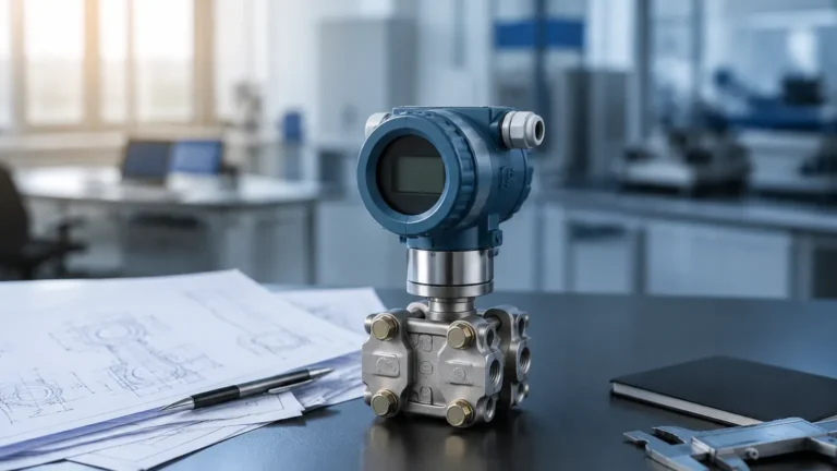
API 2350 5th Edition Overfill Prevention Process Components
API 2350 5th Edition Overfill Prevention Process Components
In the petroleum and chemical processing industries, the prevention of tank overfills is a critical safety and environmental priority. The American Petroleum Institute (API) Standard 2350, specifically the 5th edition, provides the industry-standard framework for Overfill Protection Processes (OPP) for tanks in petroleum facilities. Understanding the api 2350 5th edition overfill prevention process components is essential for engineers and plant managers tasked with designing, operating, and maintaining storage tank systems that comply with modern safety protocols.
The 5th edition emphasizes a management system approach, integrating hardware, software, and human intervention to mitigate the risk of overfill. This article explores the technical principles of level measurement, the specific components required by the standard, and the selection criteria for ensuring a robust safety layer.
Understanding API 2350 5th Edition Standards
API 2350 5th Edition applies to atmospheric storage tanks that receive Class I (flammable) and Class II (combustible) liquids. The standard categorizes tanks into three levels based on the degree of automation and the presence of an Automated Overfill Prevention System (AOPS):
1. Category I (Manual): Relies on manual gauging and human intervention. These tanks have the highest requirement for operator attendance during receipt.
2. Category II (Semiautomatic): Equipped with a high-level alarm (HLA) that alerts an operator, who must then manually terminate the flow.
3. Category III (Automatic): Features an independent Automated Overfill Prevention System (AOPS) that can terminate the flow without human intervention if a critical level is reached.
The transition between these categories depends heavily on the reliability of the level measurement instruments and the integration of the various process components.
Measurement Principles for Overfill Prevention
Before selecting specific components, it is necessary to understand the physical principles governing level measurement. In the context of API 2350, sensors must provide high reliability and repeatability. Common technologies used by manufacturers like Welk include:
Radar Level Measurement (Non-Contact and Guided Wave)
Radar level meters operate on the Time-of-Flight (ToF) principle. A sensor emits electromagnetic pulses that travel to the liquid surface and reflect back. The distance is calculated based on the time taken for the pulse to return.
* 80GHz High-Frequency Radar: Ideal for overfill prevention because the narrow beam angle avoids internal tank obstructions (like agitators or ladders) and provides millimeter-level accuracy.
* Guided Wave Radar (GWR): Uses a probe to guide the pulse. This is particularly effective in tanks with heavy foam or low dielectric constant liquids where non-contact signals might dissipate.
Ultrasonic Level Sensors
Ultrasonic sensors emit sound waves that reflect off the liquid surface. While cost-effective, they are sensitive to temperature fluctuations, heavy vapors, and vacuum conditions, which can alter the speed of sound. They are typically used in water treatment or stable chemical storage rather than high-pressure hydrocarbon tanks.
Hydrostatic Pressure Transmitters
These measure the pressure exerted by the liquid column at the bottom of the tank. While excellent for continuous level monitoring, they require accurate density data to calculate level. In API 2350 applications, they are often used as a secondary check rather than the primary high-high alarm sensor.
Point Level Switches
Unlike continuous transmitters, switches provide a discrete signal when the liquid reaches a specific height.
* Vibrating Fork Switches: These use a tuning fork that vibrates at its natural frequency. When submerged in liquid, the frequency shifts, triggering an alarm. They are highly reliable for "High-High" (HH) level detection.
* Magnetic Level Gauges: Use a float with an internal magnet to move an external indicator or trigger a magnetic switch. These provide a physical visual reference alongside electronic signals.
Key API 2350 5th Edition Overfill Prevention Process Components
A compliant overfill prevention system is comprised of several distinct layers. The api 2350 5th edition overfill prevention process components must work in unison to ensure that if one component fails, the system still reaches a safe state.
1. The Primary Sensor (Level Instrument)
This is the first point of detection. Under the 5th edition, for Category II and III tanks, the sensor must be independent of the tank's regulatory gauging system. If a radar meter is used for inventory management, a separate vibrating fork switch or a second radar unit is required for the overfill alarm to prevent common-cause failures.
2. The Logic Solver
In an AOPS (Category III), the logic solver is the "brain" of the system. It receives the signal from the sensor and determines if the level has exceeded the "High-High" setpoint. This is typically a Safety Instrumented System (SIS) or a dedicated PLC that is separate from the basic process control system (BPCS).
3. Final Control Elements
These are the components that physically stop the flow of liquid into the tank. They include:
* Emergency Shutdown Valves (ESV): Automated valves that close upon receiving a signal from the logic solver.
* Pump Starters: Circuits that automatically cut power to the transfer pumps.
4. Annunciators and Alarms
For Category II tanks, the component is an audible and visual alarm located where the operator can immediately respond. The 5th edition specifies that the alarm must be triggered early enough to allow the operator the "Response Time" (RT) necessary to manually stop the flow before the tank reaches the Critical High (CH) level.
Technical Selection Table
When evaluating api 2350 5th edition overfill prevention process components, engineers should compare technologies based on the specific tank environment.
| Technology | Measurement Principle | Best Use Case | API 2350 Suitability |
| :— | :— | :— | :— |
| 80GHz Radar | Non-contact EM Pulse | Large crude oil tanks, volatile chemicals | Excellent (Primary or Secondary) |
| Guided Wave Radar | Contact EM Pulse | Small vessels with foam or turbulence | Excellent (High Reliability) |
| Vibrating Fork | Frequency Shift | High-High (HH) point detection | Standard for AOPS sensors |
| Ultrasonic | Sound Wave Reflection | Water/Wastewater, non-volatile liquids | Limited (Category I or II) |
| Magnetic Gauge | Float/Magnetism | Visual local indication + Switch | Good (Redundant local check) |

Installation Considerations and Best Practices
The effectiveness of overfill prevention components depends heavily on correct installation. API 2350 5th edition emphasizes that sensors must be positioned to avoid "dead zones" and turbulence near the inlet.
* Stilling Wells: For tanks with significant surface turbulence or internal structures, installing radar or float-based sensors inside a stilling well (a vertical pipe) can stabilize the liquid surface and improve accuracy.
* Nozzle Placement: Sensors should not be placed directly above the filling inlet. The incoming flow can create false readings or physical damage to the probe.
* Redundancy and Independence: To meet Category III requirements, the AOPS must be physically and electrically independent of the tank gauging system. This means separate nozzles, separate power supplies, and separate cabling.
* Proof Testing: The 5th edition mandates regular functional testing. Components should be selected that support "remote proof testing," allowing operators to verify the sensor's functionality without climbing the tank or manually raising the liquid level.
Common Risks and Limitations
Even with high-quality api 2350 5th edition overfill prevention process components, certain environmental factors can introduce risk:
1. Vapor Space Interference: In petroleum tanks, heavy hydrocarbon vapors can change the dielectric constant of the air space. High-frequency radar (80GHz) is generally immune to these changes, but ultrasonic sensors may fail.
2. Paraffin/Wax Buildup: In crude oil applications, waxy buildup on sensors can cause "sticking" in mechanical switches. Non-contact radar is the preferred solution to mitigate this risk.
3. Human Factors: For Category I and II systems, the human element is the weakest link. API 2350 requires documented procedures and training to ensure that operators understand the urgency of an overfill alarm.
4. Response Time (RT) Calculation: A common error is failing to account for the time it takes for a valve to fully close. The "High-High" alarm must be set at a level that accounts for the maximum flow rate and the physical closing time of the ESV.
Frequently Asked Questions (FAQs)
Q: Can I use my existing tank gauge for API 2350 compliance?
A: Only if you are operating a Category I or II tank and have a separate, independent high-level alarm. For Category III (AOPS), the overfill prevention sensor must be entirely independent of the gauge used for inventory and process control.
Q: What is the difference between the 4th and 5th editions regarding components?
A: The 5th edition provides clearer definitions for "transpired time" and operator response requirements. It also places a heavier emphasis on the lifecycle management of the components, including more rigorous testing and documentation standards.
Q: Are wireless sensors allowed for overfill prevention?
A: While API 2350 does not strictly forbid wireless, the reliability and latency of the wireless network must be evaluated against the required Safety Integrity Level (SIL). Most Category III systems still prefer hard-wired connections for the final control element.
Conclusion
Implementing api 2350 5th edition overfill prevention process components requires a holistic view of tank safety. By selecting the appropriate measurement principle—such as high-frequency radar for continuous monitoring or vibrating forks for point level detection—and ensuring system independence, facilities can significantly reduce the risk of catastrophic spills. For engineers looking to upgrade their tank farms, reviewing the latest in sensor technology is the first step toward compliance.
For more information on selecting the right instrumentation for your specific application, you can visit the Main Page to explore a wide range of radar, ultrasonic, and magnetic level solutions designed for industrial automation.
Download API 2350 5th Edition Overfill Prevention Process Components as a PDF