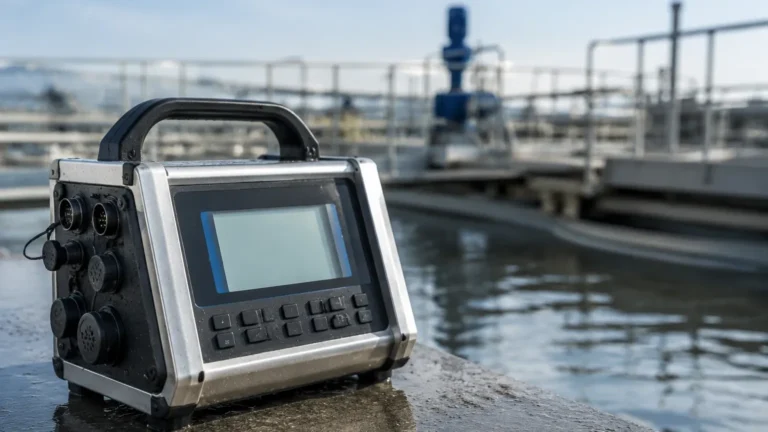
Capacitance Level Transmitter
Capacitance Level Transmitter
In the field of industrial process control, the capacitance level transmitter remains a cornerstone technology for continuous level measurement. Known for its robustness in high-pressure and high-temperature environments, this technology leverages the electrical properties of the stored material to provide accurate data. Unlike mechanical systems that rely on floats or moving parts, capacitance-based instruments offer a solid-state solution that minimizes maintenance while handling some of the most challenging media in the chemical, oil and gas, and water treatment sectors.
Understanding the engineering principles, selection criteria, and installation nuances is essential for ensuring long-term reliability. This guide provides a technical overview of how these transmitters function and how to integrate them into modern industrial automation systems.
Measurement Principle of Capacitance Technology
The operation of a capacitance level transmitter is based on the fundamental physics of a capacitor. A simple capacitor consists of two conductive plates separated by an insulating material known as a dielectric. The ability of this setup to store an electrical charge is defined as capacitance (C), which is calculated using the formula:
C = ε × (A / d)
Where:
* ε (Epsilon): The dielectric constant of the material between the plates.
* A: The surface area of the plates.
* d: The distance between the plates.
1200
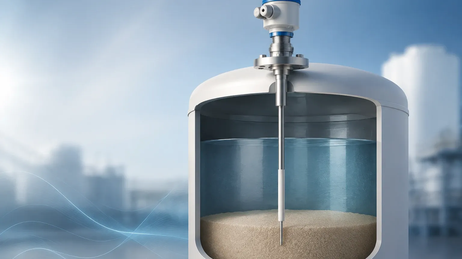
In a typical industrial tank application, the transmitter probe (an insulated or bare metal rod) acts as one plate of the capacitor, and the tank wall (if metal) acts as the second plate. If the tank is non-conductive (e.g., fiberglass or plastic), a secondary reference rod or a ground strap is used as the second plate.
As the level of the liquid or solid rises, it displaces the air or gas above it. Since most process materials have a higher dielectric constant than air (which has a dielectric constant of approximately 1), the total capacitance of the system increases in direct proportion to the level of the material. The electronics in the transmitter head convert this change in capacitance into a standardized linear signal, typically 4-20mA or a digital protocol like HART or Modbus.
RF Admittance: An Advanced Variation
Modern capacitance level transmitters often utilize RF (Radio Frequency) Admittance technology. While standard capacitance measurement only measures the capacitive reactance, RF Admittance measures both resistance and capacitance (impedance). This is particularly useful in applications where material "build-up" or coating occurs on the probe. By processing the phase shift of the signal, the transmitter can distinguish between the actual level of the liquid and the conductive coating left on the probe, effectively "ignoring" the build-up and preventing false high-level readings.
Key Components and Construction
A capacitance level transmitter consists of three primary elements:
1. The Electronic Housing: Contains the signal processing circuitry, calibration interface, and terminal blocks for wiring. These are often rated for hazardous areas (Ex-proof or Intrinsically Safe).
2. The Process Connection: The threaded or flanged interface that secures the probe to the vessel. This must be compatible with the tank's pressure and temperature ratings.
3. The Probe (Sensor): The sensing element that extends into the medium. Probes can be rigid rods (for shorter tanks, typically up to 3 or 4 meters) or flexible cables (for deep silos or tanks reaching 30 meters or more).
Insulation Materials
Probes are frequently coated with insulating materials such as PTFE (Teflon), PFA, or FEP. Insulation is mandatory when measuring conductive liquids (like water or acids) to prevent a short circuit between the probe and the tank wall. For non-conductive materials like oils or dry bulk solids, bare metal probes may be used, though insulation is often preferred for chemical resistance.
Selection Criteria for Capacitance Level Transmitters
Choosing the right capacitance level transmitter requires a thorough analysis of the process environment. The following table summarizes the primary factors to consider during the specification phase.
Selection Table: Application Parameters
| Parameter | Requirement/Impact | Recommendation |
| :— | :— | :— |
| Dielectric Constant (ε) | Must be stable and significantly different from air. | ε > 1.5 for reliable measurement. |
| Conductivity | Determines if the probe needs insulation. | Use PTFE/PFA insulated probes for conductive media. |
| Tank Material | Conductive tanks act as a ground; non-conductive tanks do not. | Install a reference rod or ground tube in plastic/FRP tanks. |
| Temperature | High temperatures can degrade probe insulation. | Specify high-temp ceramics or specialized PFA for >200°C. |
| Pressure | High pressure affects the seal at the process connection. | Ensure the flange/thread rating matches the vessel MWP. |
| Material State | Liquids vs. Solids. | Use cable probes for solids to withstand lateral pull forces. |
| Coating/Build-up | Conductive coatings can cause measurement errors. | Select RF Admittance versions for sticky or viscous media. |
Practical Installation Considerations
Correct installation is the most critical factor in the performance of a capacitance level transmitter. Because the measurement relies on the electrical relationship between the probe and the ground, the following guidelines should be followed:
1. Grounding and Reference
For a capacitance system to work, there must be a continuous electrical path back to the transmitter's ground. In metal tanks, the process connection usually provides this path. However, in lined tanks or plastic vessels, a reference electrode (ground rod) must be installed parallel to the measuring probe. Without a stable reference, the signal will drift or fail to respond to level changes.
2. Mounting Position
The probe should be mounted away from the tank's filling inlet to avoid the direct impact of falling material, which can cause physical damage or erratic readings. It should also be kept at a consistent distance from the tank wall and internal structures like agitators or baffles. If the probe is too close to a wall, the "d" (distance) in the capacitance formula becomes small, making the system overly sensitive to minor movements or build-up in that specific area.
3. The "Dead Zone"
There is typically a small inactive area at the very top of the probe (near the process connection) and at the very bottom. These are known as dead zones. When designing the tank's operating range, ensure that the 0% and 100% levels fall within the active sensing length of the probe to maintain linearity.
4. Bypasses and Stilling Wells
In applications with heavy turbulence or surface foam, installing the capacitance level transmitter inside a stilling well or a bypass chamber can provide a stable environment for measurement. The metallic pipe of the stilling well also acts as an excellent concentric ground reference, which can increase the sensitivity of the measurement for low-dielectric liquids.
Advantages and Limitations
Advantages
* No Moving Parts: High reliability and low maintenance compared to float-based systems.
* Extreme Conditions: Can operate in temperatures ranging from -200°C to over 400°C and pressures exceeding 100 bar.
* Versatility: Capable of measuring liquids, slurries, and granular solids.
* Interface Measurement: Excellent for detecting the interface between two non-mixing liquids with different dielectric constants (e.g., oil and water).
Limitations
* Dielectric Sensitivity: If the dielectric constant of the material changes significantly (due to temperature shifts or changes in chemical composition), the transmitter may require recalibration.
* Build-up: While RF Admittance mitigates this, heavy conductive coating can still pose challenges for standard capacitance units.
* Installation Rigidity: Probes must remain stationary. Any bending or movement of the probe relative to the tank wall will change the capacitance and cause errors.
Comparison with Other Technologies
When evaluating level measurement solutions, engineers often compare capacitance with Radar or Ultrasonic technologies. For comprehensive product details and technical support on these various types, engineers should consult the Main Page of specialized manufacturers.
* Capacitance vs. Ultrasonic: Ultrasonic sensors struggle with dust, foam, and vacuum conditions, whereas capacitance transmitters are unaffected by these factors. However, capacitance requires contact with the medium, while ultrasonic is non-contact.
* Capacitance vs. Radar: Radar (GWR or Non-contact) is often more expensive but is less affected by changes in the dielectric constant. Capacitance remains the preferred choice for high-pressure/high-temperature applications where radar electronics might be cost-prohibitive or physically limited.
Calibration Procedures
Calibration of a capacitance level transmitter typically involves setting the "Zero" and "Span" points.
1. Zero Calibration: Performed when the tank is at its lowest desired level (0%). The transmitter records the base capacitance of the empty probe.
2. Span Calibration: Performed when the tank is at its highest desired level (100%). The transmitter records the capacitance with the probe submerged.
Many modern transmitters feature "one-touch" calibration or allow for dry calibration if the dielectric constant of the material is known. However, for maximum accuracy, a wet calibration (performing the steps with actual material) is always recommended.
Frequently Asked Questions (FAQ)
Q: Can a capacitance level transmitter measure dry powders?
A: Yes. Capacitance is highly effective for dry solids like plastic pellets, cement, or grain, provided the moisture content remains relatively stable, as moisture significantly alters the dielectric constant.
Q: What happens if the probe insulation is damaged?
A: If the insulation on a probe in a conductive liquid is breached, the probe will short to the liquid, usually resulting in a "high-level" error signal (e.g., 22mA). Regular inspection is recommended in abrasive applications.
Q: Is it possible to cut a rod probe to length in the field?
A: Some models allow for field-shortening of the probe, but this requires recalibration of the electronics. Always check the manufacturer’s manual before cutting, as some probes have specialized end-seals that cannot be disturbed.
Q: How does temperature affect the reading?
A: Temperature affects both the dielectric constant of the material and the physical dimensions of the probe (thermal expansion). High-quality transmitters include temperature compensation circuits to minimize these effects.
Conclusion
The capacitance level transmitter is a versatile and durable tool for industrial level monitoring. By understanding the dielectric properties of the process media and ensuring a proper electrical ground reference, users can achieve high-precision measurements even in the most demanding environments. Whether used for simple water storage or complex chemical reactors, these instruments provide the data necessary for safe and efficient process automation. For those seeking specific model specifications or application-specific advice, visiting the Main Page of an experienced instrument manufacturer is the recommended next step in the procurement process.