Hydraulic Oil Level Sensor
Hydraulic Oil Level Sensor
In industrial hydraulic systems, the hydraulic oil level sensor serves as a critical component for ensuring system reliability, safety, and efficiency. Hydraulic fluids are the lifeblood of machinery used in construction, manufacturing, and aerospace. Maintaining the correct fluid volume is not merely a matter of performance; it is a preventative measure against pump cavitation, overheating, and catastrophic component failure. This guide explores the technical principles, selection criteria, and installation requirements for modern hydraulic oil level measurement technologies.
Understanding Measurement Principles
Selecting the right hydraulic oil level sensor requires an understanding of how different technologies interact with the physical properties of hydraulic fluid, such as viscosity, dielectric constant, and temperature sensitivity.
Hydrostatic Pressure Measurement
Hydrostatic sensors operate on the principle that the pressure at the bottom of a reservoir is directly proportional to the height of the liquid column above it. The formula used is $P = \rho \cdot g \cdot h$, where $P$ is pressure, $\rho$ is the density of the oil, $g$ is gravity, and $h$ is the liquid level.
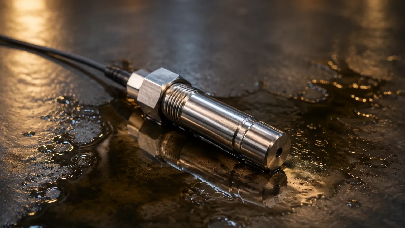
In hydraulic applications, these sensors are often submersible or mounted to the bottom of the tank via a threaded connection. Because hydraulic oil density changes with temperature, high-precision hydrostatic sensors often include integrated temperature compensation to maintain accuracy across varying operating conditions.
Ultrasonic Time-of-Flight
Ultrasonic sensors are non-contact devices that emit high-frequency sound pulses. These pulses travel through the air, reflect off the oil surface, and return to the sensor. The distance is calculated based on the time-of-flight and the speed of sound. While effective for many applications, ultrasonic sensors can be affected by heavy foam on the oil surface or significant temperature gradients within the tank's headspace, which alter the speed of sound.
Radar (Microwave) Technology
Radar level meters, specifically Frequency Modulated Continuous Wave (FMCW) radar, represent the high-end of measurement technology. These sensors emit microwave signals. Like ultrasonic sensors, they measure time-of-flight, but because microwaves are electromagnetic, they are unaffected by air temperature, vacuum, or pressure. For hydraulic oils with low dielectric constants, high-frequency radar (such as 80 GHz) provides a focused beam that can accurately detect the oil surface even in narrow reservoirs with internal obstructions.
Capacitive Level Sensing
Capacitive sensors treat the oil and the air in the tank as dielectric materials between two conductors (the sensor probe and the tank wall). As the oil level rises, the overall capacitance of the system changes. This technology is robust and has no moving parts, making it suitable for mobile hydraulic equipment. However, it requires calibration to the specific type of hydraulic oil being used.
Float-Based (Magnetic) Sensors
These are mechanical or electro-mechanical devices where a float containing a magnet moves along a stem. The magnet actuates reed switches or a continuous resistive chain inside the stem. While simpler and often more cost-effective, they are contact-based and may be susceptible to mechanical wear or sticking if the hydraulic oil becomes contaminated with metal shavings or sludge.
Key Evaluation Criteria for Selection
When specifying a hydraulic oil level sensor, engineers must look beyond the basic measurement range. The following factors are decisive in ensuring long-term performance:
1. Fluid Compatibility: Hydraulic oils can be mineral-based, synthetic, or water-glycol mixtures. The sensor materials (316L stainless steel, FKM/Viton seals, etc.) must be chemically resistant to the specific fluid.
2. Operating Pressure: While many reservoirs are vented to the atmosphere, some hydraulic systems operate under pressurized conditions. The sensor must be rated for the maximum system pressure, often expressed in bar or MPa.
3. Temperature Range: Hydraulic systems can operate from sub-zero startup conditions to over 80°C (176°F) during peak load. The sensor's electronics and housing must withstand these cycles.
4. Output Signals: Integration with PLCs or industrial IoT gateways requires standard outputs such as 4-20 mA, 0-10 V, or digital protocols like Modbus RTU and IO-Link.
For a comprehensive overview of available industrial instrumentation, you may refer to the Main Page of our technical catalog.
Technical Selection Table
| Technology | Accuracy | Max Temperature | Media Contact | Relative Cost | Best Use Case |
| :— | :— | :— | :— | :— | :— |
| Radar | ±1 mm | Up to +250°C | Non-contact | High | Precision monitoring in high-temp/pressure |
| Ultrasonic | ±0.25% FS | Up to +80°C | Non-contact | Medium | Standard atmospheric vented tanks |
| Hydrostatic | ±0.5% FS | Up to +100°C | Contact | Medium | Deep reservoirs or pressurized sumps |
| Capacitive | ±1% FS | Up to +150°C | Contact | Medium | Mobile hydraulics and high-vibration |
| Magnetic Float| ±5 mm | Up to +120°C | Contact | Low | Simple level switching and alarms |
Installation Considerations
Proper installation is as important as the technology choice itself. Incorrect placement can lead to false readings or premature sensor failure.
* Turbulence and Baffles: Hydraulic return lines often create turbulence and aeration. Sensors should be installed behind baffles or in a stilling well to ensure a stable surface for measurement.
* Dead Zones (Blocking Distance): Both radar and ultrasonic sensors have a "dead zone" directly beneath the sensor face where measurement is impossible. Ensure the sensor is mounted high enough that the maximum oil level does not enter this zone.
* Mounting Orientation: Hydrostatic sensors should be mounted away from the pump intake to avoid pressure fluctuations caused by fluid velocity. Non-contact sensors must be mounted perfectly perpendicular to the oil surface.
* Tank Geometry: In narrow tanks, radar or ultrasonic signals may reflect off the walls. Using sensors with a narrow beam angle or utilizing "false signal suppression" software can mitigate these reflections.
Common Risks and Limitations
Despite advancements in sensor technology, certain environmental factors remain challenging for a hydraulic oil level sensor:
* Foaming: Excessive foaming in hydraulic oil, often caused by air leaks in the suction line, can absorb ultrasonic signals or create a "false floor" for radar sensors. In such cases, hydrostatic or capacitive sensors are preferred.
* Dielectric Constant Changes: If a system switches from a mineral oil to a synthetic fire-resistant fluid, a capacitive or radar sensor may require recalibration due to the change in the fluid's dielectric properties.
* Contamination: Metallic particles in the oil can interfere with magnetic float sensors. Regular oil filtration and the use of non-contact sensors help mitigate this risk.
* Condensation: In outdoor or humid environments, water can condense on the face of non-contact sensors. Selecting sensors with specialized coatings or heated faces can prevent signal attenuation.
Maintenance and Calibration
Industrial hydraulic systems require periodic maintenance of level instrumentation. For contact-based sensors, visual inspection for coating or buildup is necessary every 6 to 12 months. For hydrostatic sensors, the vent tube in the cable (which compensates for atmospheric pressure) must remain clear and dry. If the tube becomes blocked, the sensor will drift as barometric pressure changes.
Calibration should be verified annually using a manual dipstick or sight glass as a reference. Most digital sensors allow for "field teaching," where the 4 mA (empty) and 20 mA (full) points can be adjusted via a local display or a connected laptop.
Frequently Asked Questions (FAQ)
Q: Can I use a standard water level sensor for hydraulic oil?
A: It is not recommended. Hydraulic oil has a lower density than water (typically 0.85 to 0.92 g/cm³), which will cause a hydrostatic sensor calibrated for water to under-read. Additionally, the seal materials in a water sensor may degrade when exposed to hydraulic fluids.
Q: What is the benefit of using IO-Link with a hydraulic oil level sensor?
A: IO-Link allows for remote parameterization and provides diagnostic data, such as internal sensor temperature and signal strength. This enables predictive maintenance, allowing operators to clean or replace a sensor before it fails.
Q: How do I measure oil level in a tank that is constantly moving, such as on a crane?
A: For mobile applications, capacitive sensors or guided wave radar (GWR) are ideal. GWR uses a physical probe to guide the microwave signal, making it immune to the sloshing and surface movement common in mobile machinery.
Q: Is non-contact radar worth the extra cost over ultrasonic?
A: If the reservoir is subject to temperature swings or if the oil is prone to slight outgassing, radar is significantly more reliable. For simple, indoor, ambient-temperature tanks, ultrasonic is usually sufficient.
Conclusion
The selection of a hydraulic oil level sensor is a balance between technical requirements and budget constraints. While simple float switches provide basic high/low alarms, continuous monitoring through radar or hydrostatic transmitters allows for sophisticated system analytics and leak detection. By understanding the measurement principles and the specific challenges of the hydraulic environment, engineers can specify a solution that enhances the longevity of the entire hydraulic circuit. For further technical specifications and product comparisons, visit the Main Page.