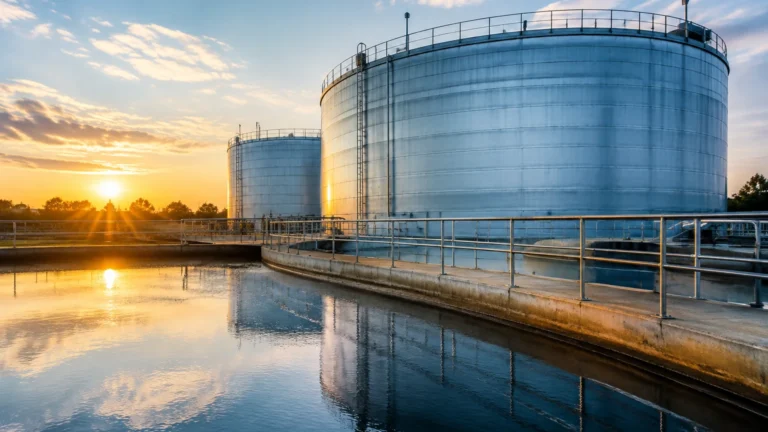
Gas and Oil Separator
Gas and Oil Separator
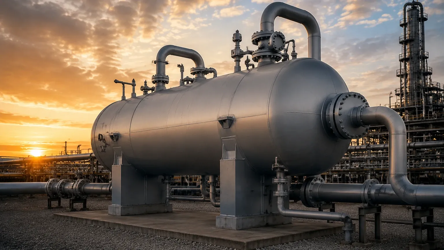
In the upstream and midstream sectors of the oil and gas industry, the gas and oil separator is a fundamental component of the production process. These vessels are designed to split the complex stream of well fluids—typically a mixture of crude oil, natural gas, water, and sometimes solids like sand—into their respective phases. Efficient separation is critical not only for product quality but also for the protection of downstream equipment such as compressors, pumps, and storage tanks.
Central to the operation of any gas and oil separator is the precise measurement of liquid levels and interfaces. Without accurate data, operators risk "carry-over" (liquid entering the gas line) or "carry-under" (gas entering the liquid line), both of which can lead to equipment failure and significant economic loss. As a professional manufacturer, Welk provides specialized level measurement instruments designed to withstand the high pressures and corrosive environments typical of these separation processes.
Principles of Level Measurement in Separator Vessels
Before selecting a specific instrument, it is essential to understand the physical principles that govern level measurement within a gas and oil separator. Because these vessels often contain multiple layers (gas, oil, and water), the technology must be capable of distinguishing between different fluid densities and dielectric properties.
Guided Wave Radar (GWR)
Guided Wave Radar is based on the principle of Time Domain Reflectometry (TDR). A low-energy microwave pulse is sent down a probe (waveguide). When the pulse reaches the surface of the medium, a portion of the energy is reflected back to the transmitter. In a 3-phase separator, GWR is particularly effective for interface measurement. Because oil has a low dielectric constant (εr ≈ 2.0) and water has a high dielectric constant (εr ≈ 80), the microwave pulse passes through the oil layer and reflects off the oil-water interface. This allows for the simultaneous measurement of the total level and the interface level.
Non-Contact Radar
Non-contact radar transmitters emit radio frequency signals (typically in the 26 GHz or 80 GHz range) that reflect off the top liquid surface. This technology is ideal for measuring the total liquid level in a gas and oil separator where the probe cannot touch the medium due to high turbulence or corrosive properties. However, non-contact radar is generally less effective for interface measurement compared to GWR, as the signal often cannot penetrate the top layer sufficiently to detect the water level below.
Magnetic Level Gauges (MLG)
Magnetic level gauges utilize a float containing an internal magnet assembly. This float is designed to have a specific buoyancy that matches either the oil-gas interface or the oil-water interface. As the fluid level rises or falls, the float moves accordingly, flipping magnetic flags on an external scale for visual indication. For automated control, these can be equipped with reed chain transmitters or magnetostrictive sensors to provide a 4-20mA signal to the control room.
Differential Pressure (DP) Transmitters
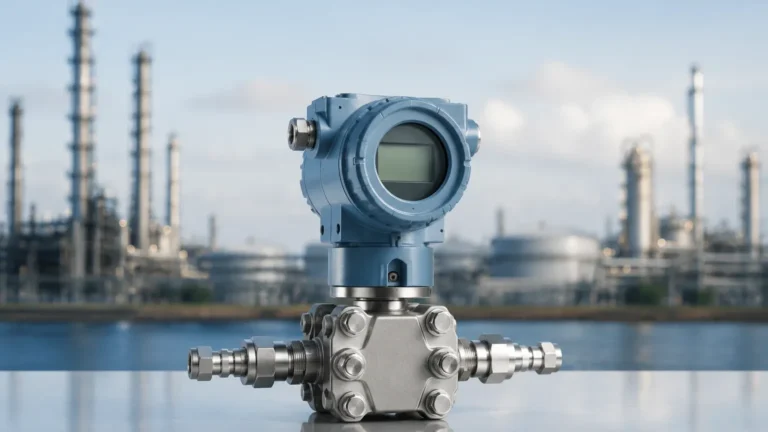
DP transmitters measure the hydrostatic pressure exerted by the liquid column. By calculating the difference between the pressure at the bottom of the vessel and the gas pressure at the top, the level can be inferred. While cost-effective, DP measurement is highly sensitive to changes in fluid density, which can fluctuate in a separator based on temperature and the specific gravity of the incoming crude.
The Role of Level Measurement in 2-Phase vs. 3-Phase Separators
The configuration of the gas and oil separator dictates the complexity of the level measurement required.
2-Phase Separators
In a 2-phase separator, the goal is to separate gas from the total liquid (oil and water combined). Here, the primary concern is preventing the liquid level from reaching the gas outlet. A single-point level switch or a continuous level transmitter is used to maintain the liquid within a safe operating range. High-level alarms are critical to prevent liquid slugs from entering gas compressors.
3-Phase Separators
3-phase separators are more complex as they must separate gas, oil, and water. This requires two distinct level measurements:
1. Total Liquid Level: The boundary between the gas and the oil.
2. Interface Level: The boundary between the oil and the water.
Accurate interface control is vital for the "water draw-off" process. If the interface level is too high, water may be discharged with the oil; if it is too low, oil may be lost into the produced water treatment system. For detailed information on instruments capable of handling these dual-layer measurements, engineers can refer to the Main Page of the Welk product catalog.
Technical Selection Criteria for Separator Instrumentation
Choosing the right level sensor involves evaluating the process conditions against the limitations of each technology. The following table provides a general comparison for common gas and oil separator applications:
| Technology | Measurement Type | Pressure Range | Temp. Range | Suitability for Foam | Interface Capable |
| :— | :— | :— | :— | :— | :— |
| Guided Wave Radar | Continuous | Up to 40 MPa | -196 to +450°C | Excellent | Yes |
| Non-Contact Radar | Continuous | Up to 16 MPa | -40 to +200°C | Moderate | No |
| Magnetic Gauge | Visual/Continuous | Up to 32 MPa | -196 to +400°C | Good | Yes |
| Ultrasonic | Continuous | Atmospheric | -40 to +80°C | Poor | No |
| Displacer | Continuous | Up to 25 MPa | -196 to +400°C | Good | Yes |
Key Evaluation Factors
* Fluid Density: If the specific gravity of the oil and water are too close (e.g., heavy crude), magnetic floats and displacers may struggle to find the interface.
* Dielectric Constant: For radar systems, a minimum dielectric difference is required to distinguish between layers.
* Presence of H2S: In "sour" service, all wetted parts must comply with NACE MR0175/ISO 15156 standards to prevent stress corrosion cracking.
* Vessel Geometry: Internal baffles, weirs, and mist extractors can create obstructions for radar signals, requiring careful placement or the use of stilling wells.
Installation and Engineering Best Practices
Proper installation is as important as the technology itself. In a gas and oil separator, the environment is often turbulent due to the high-velocity inflow of well fluids.
1. Stilling Wells and Bypass Chambers: To protect the sensor from turbulence and foam, GWR probes and magnetic floats are often installed in a bypass chamber (side-mounted) or a stilling well (internal pipe). This provides a "quiet" zone for more stable measurements.
2. Nozzle Positioning: Level transmitters should be located away from the fluid inlet to avoid direct impingement of the process stream, which can cause physical damage or signal noise.
3. Venting and Equalization: For bypass chambers, ensure that both the liquid and gas phases are properly equalized with the main vessel to prevent false level readings caused by pressure differentials.
4. Calibration for Density: For hydrostatic and displacement-based sensors, the instrument must be calibrated using the actual operating densities of the oil and water at process temperature (e.g., 60°C), rather than ambient conditions.
Challenges and Limitations: The "Rag Layer"
One of the most significant challenges in a gas and oil separator is the formation of an emulsion or "rag layer." This is a middle layer where oil and water have not fully separated, often stabilized by solids or surfactants.
* Impact on Radar: A thick rag layer can attenuate radar signals, making the interface reflection indistinct or "lost." In such cases, high-power GWR or specialized algorithms are required to track the top of the emulsion.
* Impact on Buoyancy: Emulsions have a density gradient. A magnetic float calibrated for a clean interface may sit at an unpredictable height within the rag layer.
* Mitigation: Chemical demulsifiers and heat are often used to minimize the rag layer, but level instruments must be selected with the realization that a clean interface is not always present.
Frequently Asked Questions (FAQ)
Q: Can ultrasonic sensors be used in high-pressure gas and oil separators?
A: Generally, no. Ultrasonic sensors rely on sound waves, which are affected by gas composition, pressure, and temperature. In high-pressure separators, the high density of the gas phase and the presence of methane/CO2 significantly alter the speed of sound, leading to large errors. Radar is the preferred non-contact alternative.
Q: How do I handle foaming in the separator?
A: Foam is common when gas evolves rapidly from the oil. Guided Wave Radar is the most robust technology for foam, as the high-frequency pulse can usually penetrate light foam to find the true liquid level. Non-contact radar may see the top of the foam as the level.
Q: What maintenance is required for level instruments in oil service?
A: Paraffin and scale buildup are the primary concerns. Magnetic gauges and GWR probes should be inspected periodically for coating. Some GWR transmitters feature advanced diagnostics that can alert operators when signal strength decreases due to buildup.
Q: Is it possible to measure level in a separator with a 100% gas-tight seal?
A: Yes. Magnetic level gauges and radar transmitters with hermetic pressure seals (often using glass-to-metal or ceramic seals) are designed specifically for high-pressure containment in the oil and gas industry.
Conclusion
The efficiency of a gas and oil separator depends heavily on the reliability of its level instrumentation. By understanding the measurement principles—from the dielectric-based tracking of Guided Wave Radar to the buoyancy-based tracking of Magnetic Gauges—engineers can design systems that maximize throughput and protect downstream assets. When specifying equipment, it is vital to confirm the process fluid properties, pressure ratings, and the potential for emulsion layers. For those seeking robust and cost-effective level measurement solutions tailored for industrial automation, exploring the professional range of sensors available on the Welk Main Page is a recommended next step in the engineering process.