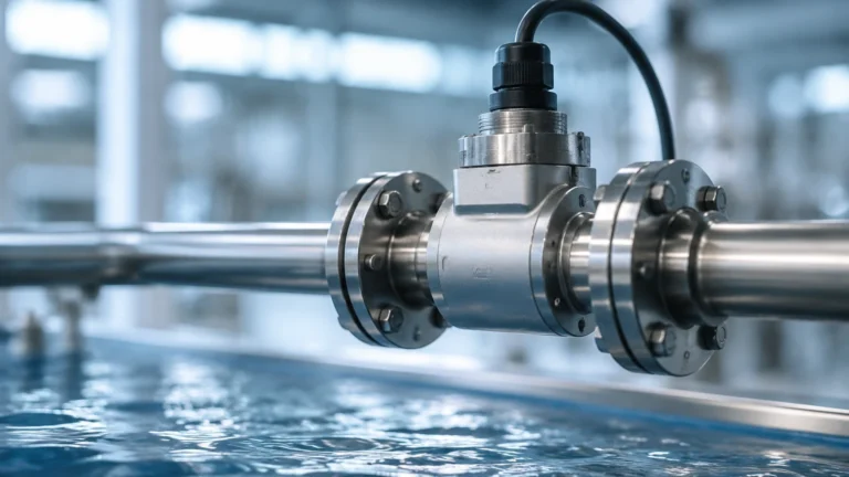
Brine Tank Salt Level Sensor
Brine Tank Salt Level Sensor
In industrial and commercial water softening systems, the brine tank is a critical component that requires consistent monitoring. A brine tank salt level sensor is designed to automate the tracking of salt inventory and brine levels, ensuring that the regeneration process of ion-exchange resins is never interrupted by a lack of regenerant. Inadequate salt levels lead to hard water breakthrough, which can cause scaling in boilers, cooling towers, and downstream piping, resulting in significant maintenance costs and energy inefficiencies.
Selecting the appropriate sensor involves understanding the unique challenges of the brine environment, including high corrosivity, the physical properties of salt (granules or pellets), and the potential for dust and moisture condensation. This guide examines the measurement principles, selection criteria, and installation best practices for salt level monitoring in industrial applications.
Measurement Principles for Brine Tanks
Level measurement in a brine tank involves two distinct substances: solid salt (sodium chloride or potassium chloride) and the liquid brine solution. Depending on the operational requirement, sensors may be used to monitor the height of the dry salt pile, the level of the liquid brine, or both.
Ultrasonic Level Measurement
Ultrasonic sensors operate on the "Time-of-Flight" (ToF) principle. The sensor emits a high-frequency sound pulse that travels through the air, reflects off the surface of the salt or liquid, and returns to the transducer. The distance is calculated based on the speed of sound.
* Advantages: Non-contact measurement prevents corrosion of the sensor face. It is generally cost-effective for standard tank heights (up to 10 meters).
* Limitations: Sound speed is affected by air temperature fluctuations. In brine tanks, heavy salt dust during refilling or significant steam/vapor can attenuate the signal.
Radar (FMCW) Level Measurement
Frequency Modulated Continuous Wave (FMCW) radar, particularly at higher frequencies like 80 GHz, is increasingly the standard for industrial brine monitoring. Radar sensors emit electromagnetic waves that reflect off the material surface.
* Advantages: Radar is unaffected by air temperature, pressure, or dust. The high frequency allows for a narrow beam angle, which is essential for avoiding internal tank obstructions like brine wells or refill pipes. For advanced radar solutions, engineers often consult the Main Page of specialized manufacturers to match frequency requirements to tank geometry.
* Limitations: Higher initial capital expenditure compared to ultrasonic or float-based systems.
Hydrostatic Pressure Measurement
Hydrostatic transmitters measure the pressure exerted by the liquid column at the bottom of the tank. This is primarily used to monitor the brine liquid level rather than the solid salt level.
* Advantages: Highly accurate for liquid volume tracking.
* Limitations: The sensor must be submerged, requiring materials like PVDF or high-grade Hastelloy to withstand the saturated salt solution. It cannot detect the height of the dry salt above the liquid line.
Laser Level Measurement
Laser sensors use a narrow light beam to measure distance. They are highly effective for solid salt measurement because the narrow beam can target specific points on an uneven salt pile.
* Advantages: Extremely precise with no beam spread, making them ideal for narrow tanks.
* Limitations: Performance can be degraded by heavy dust during pneumatic salt loading.
Technology Selection Table
When evaluating a brine tank salt level sensor, engineers should compare technologies based on the specific environment of the water treatment plant.
| Feature | Ultrasonic | Radar (80 GHz) | Hydrostatic | Laser |
| :— | :— | :— | :— | :— |
| Measurement Target | Solid or Liquid | Solid or Liquid | Liquid Only | Solid Only |
| Accuracy | ±0.25% of range | ±2 mm | ±0.1% of span | ±1 mm |
| Dust Resistance | Moderate | Excellent | N/A | Low |
| Vapor Resistance | Low | Excellent | N/A | Moderate |
| Chemical Resistance | High (Non-contact) | High (Non-contact) | Requires special alloys | High (Non-contact) |
| Typical Range | 0.25m – 12m | 0.1m – 30m+ | 0m – 20m | 0.1m – 50m |
Key Evaluation Criteria for Industrial Brine Sensors
1. Corrosive Resistance
Saturated brine is highly corrosive. Even non-contact sensors like radar and ultrasonic units must have housings and wetted parts (if any) made of corrosion-resistant materials. Common materials include Polypropylene (PP), Polyvinylidene Fluoride (PVDF), or 316L Stainless Steel with PTFE coatings. The electronics housing should ideally be rated IP66/67 or IP68 to prevent salt air from infiltrating the circuitry.
2. Surface Profiling of Solids
Salt in a brine tank does not sit flat; it forms cones (heaps) or depressions depending on whether the tank is being filled or emptied. A sensor with a wide beam angle may receive multiple reflections, leading to inaccurate readings. Modern 80 GHz radar sensors provide a narrow beam (often as small as 3 degrees), which allows the sensor to focus on a specific area of the salt pile for a more reliable average level.
3. Integration and Communication
In B2B environments, the sensor must communicate with a PLC (Programmable Logic Controller) or a Building Management System (BMS). Standard outputs include 4-20mA (HART), Modbus RTU, or Profibus. For remote facilities, IoT-enabled sensors with cellular or LoRaWAN connectivity allow for automated salt delivery scheduling by vendors.
Installation Considerations and Best Practices
Proper installation is as critical as sensor selection. Incorrect placement can lead to "false echoes" and unreliable data.
* Avoid the Fill Path: Never install the sensor directly above the salt inlet. The falling salt during a refill will block the signal and could potentially damage the instrument.
* Dead Zone (Blocking Distance): Every ultrasonic and radar sensor has a "dead zone" directly beneath the transducer (typically 50mm to 250mm). The sensor must be mounted high enough so that the maximum salt level never enters this zone.
* Nozzle Geometry: If mounting the sensor on a nozzle, ensure the nozzle is short and wide enough that the signal beam does not reflect off the nozzle walls. For 80 GHz radar, this is less of a concern due to the narrow beam, but it remains a factor for ultrasonic units.
* Internal Obstructions: Keep the sensor away from brine wells, ladders, and agitators. If obstructions are unavoidable, use a sensor with "False Echo Suppression" software to map out and ignore these static reflections.
* Positioning on the Salt Cone: To get the most accurate inventory reading, mount the sensor at approximately 1/3 of the radius from the tank wall. This position typically represents the average height of a conical pile of granular material.
Common Risks and Limitations
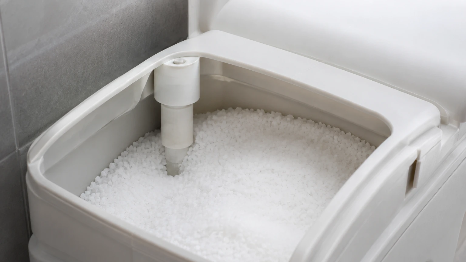
Salt Bridging
Salt bridging occurs when a hard crust forms over the liquid brine, creating an empty space underneath. A level sensor measuring from the top will detect the top of the bridge, reporting a "full" tank while the water softener is actually starved of salt. While sensors cannot "see" through a bridge, sudden stagnation in level readings despite high water usage can be used as a diagnostic alarm in the control system.
Condensation and Crusting
In humid environments, salt dust can mix with condensation on the sensor face, forming a salt crust. This crust can attenuate ultrasonic signals significantly. Radar sensors are generally more resistant to this, but periodic inspection and cleaning of the transducer face are recommended.
Signal Absorption
Dry salt has a relatively low dielectric constant. While radar can measure it, the signal reflection is weaker than that of water or metal. It is essential to select a radar sensor with high sensitivity and a high dynamic range to ensure a stable signal return from the salt surface.
Frequently Asked Questions (FAQ)
Q: Can a single sensor measure both the salt level and the brine liquid level?
A: Generally, no. A non-contact sensor (Radar/Ultrasonic) will reflect off the first surface it hits. If the salt is submerged, it reflects off the liquid. If the salt is dry and piled above the liquid, it reflects off the salt. To monitor both independently, a combination of a radar sensor (for salt) and a hydrostatic pressure transmitter (for brine) is often used.
Q: What is the maintenance schedule for a brine tank sensor?
A: In most industrial settings, a quarterly visual inspection is sufficient. Check for salt buildup on the transducer face and ensure the cable glands remain sealed against the corrosive atmosphere.
Q: Is ultrasonic or radar better for small brine tanks?
A: For small, indoor tanks with minimal dust, ultrasonic is a cost-effective solution. However, if the tank is large, located outdoors, or filled pneumatically, radar is the more robust choice due to its immunity to air movement and dust.
Conclusion
Implementing a reliable brine tank salt level sensor is a fundamental step in optimizing industrial water treatment. By selecting the right technology—whether it be the precision of 80 GHz radar or the cost-efficiency of ultrasonic—facilities can prevent costly downtime and protect their infrastructure from the effects of hard water. When specifying a system, always confirm the chemical compatibility of wetted parts and the communication protocols required for your existing automation framework. For a comprehensive overview of available measurement technologies and technical specifications, engineers should review the product options and application support available on the Welk Main Page.